
I am text block. Click edit button to change this text. Lorem ipsum dolor sit amet, consectetur adipiscing elit. Ut elit tellus, luctus nec ullamcorper mattis, pulvinar dapibus leo.
-24%Sold out


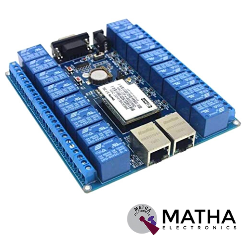
HLK-SW16 16 CHANNEL WIFI CONTROLLED RELAY BOARD
Original price was: ₹5,100.00.₹5,050.00Current price is: ₹5,050.00. inc. GST
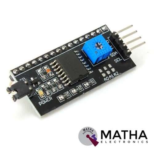
I2C MODULE WITH 16*2 CHARACTER LCD
Original price was: ₹200.00.₹150.00Current price is: ₹150.00. inc. GST
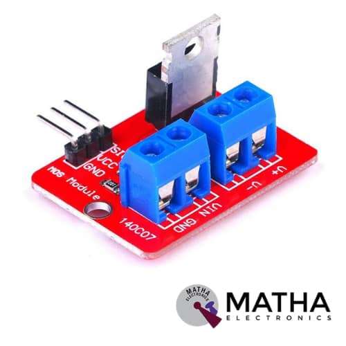
IRF520 MOSFET DRIVER MODULE SENSOR
Original price was: ₹230.00.₹175.00Current price is: ₹175.00. inc. GST
- Operating Voltage: 3.3v & 5v
- Digital level port
- Output load voltage: 0-24v
- Output load current: <5A
- The heat sink is added for currently more than 1A
- Compatible with Arduino, MCU, ARM, Raspberry pi
- PWM dimming LED used to step-less dimming, variable-speed motor
- Output PWM can be adjusted by the original IFR520 MOS
- Arduino can drive up to 24V, such as led lights, dc motors, miniature pumps, solenoid valves etc.
- Dimension:34*30*18mm
- Size: 10gm
Out of stock
Description
IRF520 is designed as a device that provides easy communication with Arduino, Raspberry pi and other 3v-5v microcontrollers. This is designed as the breakout board for IFR520 transistors. These modules can drive heavy DC loads switched from a single digital pin of the microcontroller. The pulse current through the PWM pin is used to control the pump, LED, or another device up to 20V & 5A.To control the VIN and GND, connect the power for the device to V+ and V- on screw terminals.
The Screw terminals provided on the module ensure ease of interfacing with your load and external power source. The onboard LED indicator provides a visual indication of when your load is being switched. When the signal line is high, LED lights up, and GND is connected to V-. Whereas when the signal line is low, LED turns off and GND gets disconnected from V-.the V+ and V- are continuously connected.
The main purpose of this module offers a low-cost way to drive the DC motor for robotic application. But this module is also used for high current DC loads. The load and the external power supply is interfaced using the screw terminals. An LED indicator provides a visual display when the load is being switched. We can power this device from your Arduino, VCC goes to the 5V connection and GND to the GND pin on your Arduino.
Note: Highly recommended to use Heat sinks for loads above 1A
Reviews (0)
Shipping & Delivery

Related products

1 CHANNEL 5V RELAY
- 1 channel relay board
- Operating voltage: 5V
- Maximum current: 2 A
- Relay contact current capacity of 10A @250 V AC/10A@ 30V AC
- configured as SINGLE POLE DOUBLE THROW( SPDT)
- LED status indicates relay ON/OFF state.
- Standard TTL level logic controlled
- One normally closed and one normally opened contact
- Compatible with any 5V microcontroller
- Dimension: 43*17*17mm
- Weight: 150gm

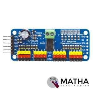
16-Channel 12-bit PWM/Servo Driver I2C interface PCA9685 for Arduino Raspberry Pi
- Adjustable frequency PWM up to about 1.6 kHz
- 12-bit resolution for each output – for servos, that means about 4us resolution at a 60Hz update rate
- Configurable push-pull or an open-drain output
- The output enable pin to quickly disable all the outputs
- Terminal block for power input
- Reverse polarity protection on the terminal block input
- Green power-good LED
- 3 pin connectors in groups of 4 so you can plug in 16 servos at once
- Chainable design
- A spot to place a big capacitor on the V+ line
- 220-ohm series resistors on all the output lines to protect them, and to make driving LEDs trivial.
- This board/chip uses an I2C 7-bit address between 0x60-0x80, selectable with jumpers.

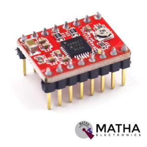
A4988 Stepper Motor
- Operating voltage supply: 8 V to 35 V
- Continuous current per phase: 1 Amp
- Maximum current per phase: 2 Amp
- Minimum logic voltage: 3V
- Maximum logic voltage: 5.5V
- Microstep resolutions: Full, 1/2, 1/4, 1/8, and 1/16
- Logic Voltage supply: 3.3 V to 5 V
- Compatible with 3V3 and 5V microcontrollers
- Our Board comes with 0.1 Ohm Sensor resistors
- Five different step resolutions: full-step, half-step, quarter-step, eighth-step, and sixteenth-step
- The Correct current decay mode (fast decay or slow decay) is selected by chopping the control
- Over-temperature thermal shutdown, under-voltage lockout, and crossover-current protection
- Short-to-ground and shorted-load protection
- 4-layer, 2 oz copper PCB for improved heat dissipation
- Exposed solderable ground pad below the driver IC on the bottom of the PCB

DRV8825 Stepper Motor
- Operating voltage: 8.2V to 45V
- Continuous current per phase: 1.5 Amp
- Maximum current per phase: 2.2 Amp
- Minimum logic voltage: 2.5V
- Maximum logic voltage: 5.25V
- Six different step resolutions: full-step, half-step, 1/4-step, 1/8-step, 1/16-step, and 1/32-step
- Compatible with 3V3 and 5V microcontrollers
- Our Board comes with 0.1 Ohm Sensor resistors
- The Correct current decay mode (fast decay or slow decay) selected by chopping control
- Over-temperature thermal shutdown, under-voltage lockout, and crossover-current protection
- Short-to-ground and shorted-load protection
- 4-layer, 2 oz copper PCB for improved heat dissipation
- Exposed solderable ground pad below the driver IC on the bottom of the PCB
- Dimensions : 15 x 20 mm.
- Weight: 4 gm.


L293D Motor Driver Shield
- L293D motor driver chip & 74HC595 shift register
- Four H-bridges
- Terminal blocks and jumper to connect external power, for separate logic/motor supplies
- Up to 4 bi-directional DC motors with individual 8-bit speed selection
- Up to 2 stepper motors (unipolar or bipolar) with single coil, double coil or interleaved stepping.
- 2 connections for 5V ‘hobby’ servos connected to the Arduino’s high-resolution dedicated timer
- 4 H-Bridges: L293D chipset provides 0.6A per bridge (1.2A peak) with thermal shutdown protection, internal kickback protection diodes. Can run motors on 4.5VDC to 25VDC.
- Pull-down resistors keep motors disabled during power-up
- Big terminal block connectors to easily hook up wires (18-26AWG) and power
- Arduino reset button brought up top
- Tested compatible with Arduino Mega 1280 & 2560, Diecimila, Duemilanove, and UNO
- PCB Size: 69 x 53 mm


L298P Motor Shield motor driver
- L298P based Arduino motor driver shield
- Operating Voltage 5V to 12V
- Motor controller L298P, Drives 2 DC motors or 1 stepper motor
- The logical part of the input voltage VD: 5V
- Driven part of the input voltage VS: VIN Input 6.5 ~ 12V, PWRIN 4.8 ~ 35V input
- The logical part of the work current Iss:<36mA
- Driven part of the operating current Io:<2A
- Current sensing 1.65V/A
- Free running stop and brake function
- Maximum power dissipation: 25W (T = 75 Celsius)
- Max current 2A per channel or 4A max (with external power supply)
- Control signal input level: High 2.3V
- Onboard Bluetooth interface, you can directly plug, no wiring required.
- The board with L298P motor drive chip, directly with the motherboard digital I/O port (D10, D11, D12, D13), without cumbersome wiring.
- Onboard buzzer (D4), you can set the reverse alarm ringtones.
- D2, D3, D5, D6, D7, D9 are not occupied by the digital interface.
- A 0 – A 5 six analogue interfaces.
- Forward and Backward steering are indicators


MACH3 interface board
- Compatible Stepper Motor Driver - Max 5 2-phase Microstep controllers
- Driver type - Pulse and Direction signal control
- Wide input voltage range: 12-24V, and with anti-reverse function.
- Output 0-10V analogue voltage for the inverter to control the spindle speed.
- Compatible with MACH3, Linux CNC (EMC2) etc. parallel-control CNC software.
- USB power supply and peripherals power phase are separate to protect computer security.
- All the signals are to-isolate which can protect your computer security.
- 5-input interface to define the Limit, Emergence-Stop, Cutter alignment, etc.
- Wide input voltage range: 12-24V, and with anti-reverse function.
- One relay output control interface, accessed by the spindle motor or the air pump, water pump, etc.
- Maximum support 5-axis stepper motor driver controllers
- Output 0-10V analogue voltage for the inverter to control the spindle speed.
- All the way to the relay output port, control spindle switch. Output port P17 mouth.
- One relay output control interface, accessed by the spindle motor or the air pump, water pump, etc.
- Weight - Approx. 75g
- Dimensions - 90 * 70 * 20mm
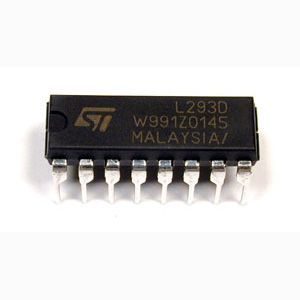
Motor Driver IC – L293D
- Can be used to run Two DC motors with the same IC.
- Speed and Direction control is possible
- Motor voltage Vcc2 (Vs): 4.5V to 36V
- Maximum Peak motor current: 1.2A
- Maximum Continuous Motor Current: 600mA
- Supply Voltage to Vcc1(vss): 4.5V to 7V
- Transition time: 300ns (at 5Vand 24V)
- Automatic Thermal shutdown is available
- Available in 16-pin DIP, TSSOP, SOIC packages
- Featuring Unit rode L293 and L293D
- Wide Supply-Voltage Range: 4.5 V to 36 V
- Separate Input-Logic Supply
- Internal ESD Protection
- Thermal Shutdown
- High-Noise-Immunity Inputs
- Output Current 1 A Per Channel (600 mA for L293D)
- Peak Output Current 2 A Per Channel (1.2 A for L293D)
- Output Clamp Diodes for Inductive Transient Suppression
Reviews
There are no reviews yet.