
I am text block. Click edit button to change this text. Lorem ipsum dolor sit amet, consectetur adipiscing elit. Ut elit tellus, luctus nec ullamcorper mattis, pulvinar dapibus leo.
-24%Sold out


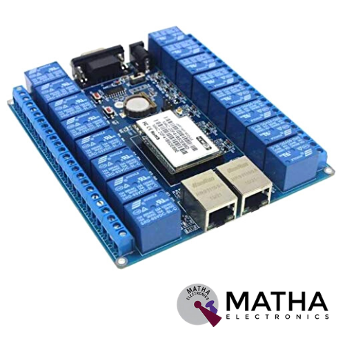
HLK-SW16 16 CHANNEL WIFI CONTROLLED RELAY BOARD
Original price was: ₹5,100.00.₹5,050.00Current price is: ₹5,050.00. inc. GST
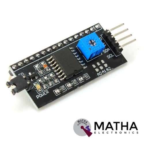
I2C MODULE WITH 16*2 CHARACTER LCD
Original price was: ₹200.00.₹150.00Current price is: ₹150.00. inc. GST
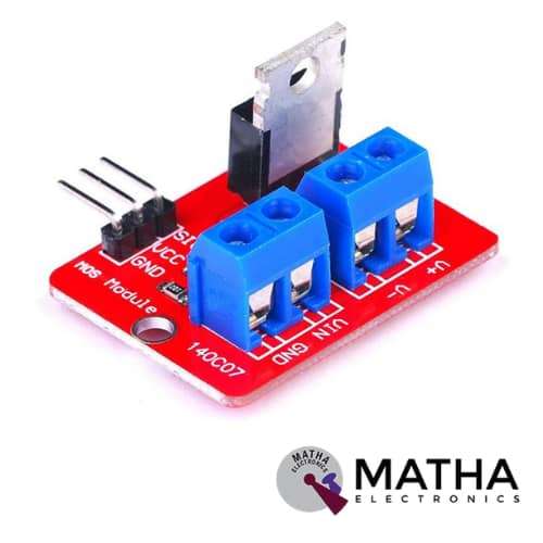
IRF520 MOSFET DRIVER MODULE SENSOR
Original price was: ₹230.00.₹175.00Current price is: ₹175.00. inc. GST
- Operating Voltage: 3.3v & 5v
- Digital level port
- Output load voltage: 0-24v
- Output load current: <5A
- The heat sink is added for currently more than 1A
- Compatible with Arduino, MCU, ARM, Raspberry pi
- PWM dimming LED used to step-less dimming, variable-speed motor
- Output PWM can be adjusted by the original IFR520 MOS
- Arduino can drive up to 24V, such as led lights, dc motors, miniature pumps, solenoid valves etc.
- Dimension:34*30*18mm
- Size: 10gm
Out of stock
Description
IRF520 is designed as a device that provides easy communication with Arduino, Raspberry pi and other 3v-5v microcontrollers. This is designed as the breakout board for IFR520 transistors. These modules can drive heavy DC loads switched from a single digital pin of the microcontroller. The pulse current through the PWM pin is used to control the pump, LED, or another device up to 20V & 5A.To control the VIN and GND, connect the power for the device to V+ and V- on screw terminals.
The Screw terminals provided on the module ensure ease of interfacing with your load and external power source. The onboard LED indicator provides a visual indication of when your load is being switched. When the signal line is high, LED lights up, and GND is connected to V-. Whereas when the signal line is low, LED turns off and GND gets disconnected from V-.the V+ and V- are continuously connected.
The main purpose of this module offers a low-cost way to drive the DC motor for robotic application. But this module is also used for high current DC loads. The load and the external power supply is interfaced using the screw terminals. An LED indicator provides a visual display when the load is being switched. We can power this device from your Arduino, VCC goes to the 5V connection and GND to the GND pin on your Arduino.
Note: Highly recommended to use Heat sinks for loads above 1A
Reviews (0)
Shipping & Delivery

Related products

“PWM Generator Module for Stepper Motor Driver with Forward and Reverse Function “
- Board can be used to generate PWM signals for the stepper motor driver
- Operating Voltage: 12VDC
- Three Frequency Range
- Forward and Reverse Function.
- It has three frequency ranges selectable via onboard jumpers.
- Frequency can be measured via PUL and common cathode (GND) ports.
- The board has two sets of power input


DM556 Digital Stepper Motor Driver with Micro Stepping 20 to 50V 5.6A
- Good high-speed performance
- Supply voltage: +50VDC
- Output current from 0.5A to 5.6A
- Pulse input frequency up to 200 kHz
- Extremely cost-effective
- Automatic idle-current reduction
- Self-test and Auto-configuration technology TTL compatible and optically isolated input
- Micro step resolutions programmable, from full-step to 102,400 steps/rev
- Suitable for 2-phase and 4-phase motors
- Support PUL/DIR and CW/CCW modes
- Anti-Resonance provides optimum torque and nulls mid-range instability
- Extra-low motor noise offers excellent quietness
- Over-voltage, over-current protection and phase error protection

DRV8825 Stepper Motor
- Operating voltage: 8.2V to 45V
- Continuous current per phase: 1.5 Amp
- Maximum current per phase: 2.2 Amp
- Minimum logic voltage: 2.5V
- Maximum logic voltage: 5.25V
- Six different step resolutions: full-step, half-step, 1/4-step, 1/8-step, 1/16-step, and 1/32-step
- Compatible with 3V3 and 5V microcontrollers
- Our Board comes with 0.1 Ohm Sensor resistors
- The Correct current decay mode (fast decay or slow decay) selected by chopping control
- Over-temperature thermal shutdown, under-voltage lockout, and crossover-current protection
- Short-to-ground and shorted-load protection
- 4-layer, 2 oz copper PCB for improved heat dissipation
- Exposed solderable ground pad below the driver IC on the bottom of the PCB
- Dimensions : 15 x 20 mm.
- Weight: 4 gm.


L298P Motor Shield motor driver
- L298P based Arduino motor driver shield
- Operating Voltage 5V to 12V
- Motor controller L298P, Drives 2 DC motors or 1 stepper motor
- The logical part of the input voltage VD: 5V
- Driven part of the input voltage VS: VIN Input 6.5 ~ 12V, PWRIN 4.8 ~ 35V input
- The logical part of the work current Iss:<36mA
- Driven part of the operating current Io:<2A
- Current sensing 1.65V/A
- Free running stop and brake function
- Maximum power dissipation: 25W (T = 75 Celsius)
- Max current 2A per channel or 4A max (with external power supply)
- Control signal input level: High 2.3V
- Onboard Bluetooth interface, you can directly plug, no wiring required.
- The board with L298P motor drive chip, directly with the motherboard digital I/O port (D10, D11, D12, D13), without cumbersome wiring.
- Onboard buzzer (D4), you can set the reverse alarm ringtones.
- D2, D3, D5, D6, D7, D9 are not occupied by the digital interface.
- A 0 – A 5 six analogue interfaces.
- Forward and Backward steering are indicators


Leadshine DMA860H
- Input voltage: Up to +80VAC or +110VDC.
- Output current Up to 7.2A.
- Pulse input frequency up to 300 KHz.
- Automatic idle-current reduction.
- Over-voltage, over-current protection.
- Suitable for 2-phase and 4-phase motors.
- Support PUL/DIR and CW/CCW modes.
- Operating Temperature : 70 C.
- High performance, cost-effective
- Self-adjustment technology
- Pure-sinusoidal current control technology
- TTL compatible and optically isolated input
- 16 selectable resolutions in decimal and binary, up to 51,200 steps/rev
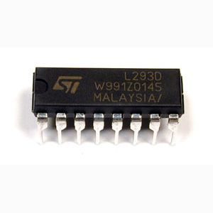
Motor Driver IC – L293D
- Can be used to run Two DC motors with the same IC.
- Speed and Direction control is possible
- Motor voltage Vcc2 (Vs): 4.5V to 36V
- Maximum Peak motor current: 1.2A
- Maximum Continuous Motor Current: 600mA
- Supply Voltage to Vcc1(vss): 4.5V to 7V
- Transition time: 300ns (at 5Vand 24V)
- Automatic Thermal shutdown is available
- Available in 16-pin DIP, TSSOP, SOIC packages
- Featuring Unit rode L293 and L293D
- Wide Supply-Voltage Range: 4.5 V to 36 V
- Separate Input-Logic Supply
- Internal ESD Protection
- Thermal Shutdown
- High-Noise-Immunity Inputs
- Output Current 1 A Per Channel (600 mA for L293D)
- Peak Output Current 2 A Per Channel (1.2 A for L293D)
- Output Clamp Diodes for Inductive Transient Suppression
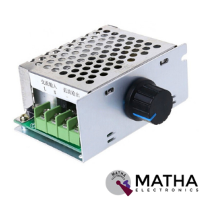
PWM DC Motor Speed Controller 20A
- Adjustable speed range: 0%-100%.
- Speed adjustment way: Potentiometer.
- Output voltage: Linear under load.
- Speed control type: Basins.
- Output voltage: Load Linear
- Type: Adjusting flow
- The motor running condition adjustment: Forward /Stop / Reverse
- Reverse polarity protection: Yes.
- Suitable Motor: DC brush motors.
Reviews
There are no reviews yet.