
I am text block. Click edit button to change this text. Lorem ipsum dolor sit amet, consectetur adipiscing elit. Ut elit tellus, luctus nec ullamcorper mattis, pulvinar dapibus leo.
Sold out


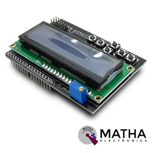
16x2 (1602) LCD Keypad Shield
Original price was: ₹450.00.₹400.00Current price is: ₹400.00. inc. GST
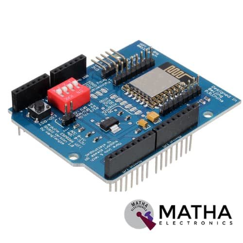
ESP8266 WIFI Shield
Original price was: ₹935.00.₹899.00Current price is: ₹899.00. inc. GST
PN532 NFC/RFID Controller Shield for Arduino
₹1,500.00 inc. GST
- PN532 chip-set
- Operating Voltage : 3.3V ~ 5v
- Support I2C, SPI
- I2C: 3.3V ~ 24V TTL
- SPI: 3.3V TTL with 100-ohm resistors in series
- Plug and play, Arduino compatible
- Built-in PCB Antenna
- Communication distance:10cm
- Easy to change mode
- NFC/RFID PN532 shield including a tuned 13.56MHz stripline antenna
- 36-pin 0.1″ header for attaching the shield to an Arduino.
- Compatible with Arduino Mega 1280 & 2560, Diecimila, Duemilanove, and UNO
Out of stock
Description
NFC/RFID Sheild was designed as a perfect tool for any 13.56MHz RFID or NFC application. This NFC shield uses the PN532 chip set. PN532 NFC Module was designed as a highly integrated radio transmission module for Near Field Communication at 13.56MHz. NFC protocol designed for smartphones and similar devices, can read and write cards and tags, interact with NFC phones, and enable communication from device to device. While the controller provides many capabilities. Our Arduino library currently only supports reading/writing tags and does not support phone-to-shield communication, tag emulation (which requires an external ‘secure element’ only available from NXP) or other more advanced features at this time.
This shield comes with a tuned 13.56MHz stripline antenna, 36-pin 0.1″ header for attaching the shield to an Arduino. In order to stack another shield on top or below, stacking headers allow pass-through stacking. This shield was designed by RF engineers using the best test equipment to create a layout. And antenna within a range of 10cm (4 inches), the maximum range possible using the 13.56MHz technology. It is quite easy to attach the shield behind a plastic plate with standoffs and still read cards through a (non-metal) barrier.
This shield supports I2C or SPI communication protocols. I2C is the default, as it uses fewer pins. Analog pins 4 and 5 are used for I2C ( you can still connect other I2C devices to the bus). And Digital #2 is used for “interrupt” notification. This means we don’t have to sit there and ‘poll’ the chip to ask a target tag has been found. The pin will pull low when a card, phone, etc is within range. The shield changes over to SPI easily where you can use any 4 digital pins by shorting two solder jumpers on the top of the PCB. These NFC/RFID Compatible with any “classic” Arduino – NG, Diecimilla, Duemilanove, UNO – as well as Mega R3 or later.
Reviews (0)
Shipping & Delivery

Related products

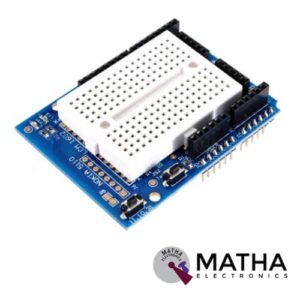
Arduino Compatible Nokia 5110 Prototype Proto Shield Expansion Board
- Supports Nokia5110 display
- Standard 0.1"x0.1" prototyping grid with big pads
- Comes with Stacking headers and plain header, choose whichever you want when soldering together
- IC pattern for adding DIP ICs up to 20 pins
- Power rails down the middle and sides
- Reset button and an extra general use button
- 2 3mm general use LEDs, red and green, as well as 2 matching resistors
- A pass-thru ICSP stacking header so you can stack any kind of shield on top, and/or use an AVR programmer
- Surface-mount chip area for up to 14 SOIC size parts
- Compatible with tiny breadboards
- Every pin is brought out
- Gold plated pads
- 2 x 0.1uF capacitors on either side for extra power stability
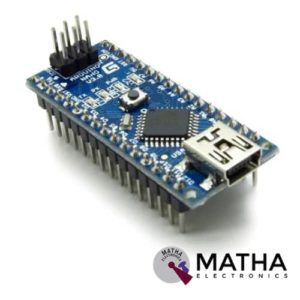

Arduino Nano V3.0
- Microcontroller: Atmel ATmega328 SMD Package
- Operating Voltage (logic level): 5 V
- Input Voltage (recommended): 7-12 V
- Input Voltage (limits): 6-20 V
- Digital I/O Pins: 14 (of which 6 provide PWM output)
- Analog Input Pins: 8
- DC Current per I/O Pin: 40 mA
- Flash Memory: 32 KB (of which 2KB used by bootloader)
- SRAM: 2 KB
- EEPROM: 1 KB
- Clock Speed: 16 MHz
- Automatic reset during program download
- Power OK blue LED
- Green (TX), red (RX) and orange (L) LED
- Auto-sensing/switching power input
- Small mini-B USB for programming and serial monitor
- ICSP header for direct program download
- Standard 0.1” spacing DIP (breadboard friendly)
- Manual reset switch
- Dimensions: 0.70” x 1.70”


ESP8266 WIFI Shield
- Operating voltage 5V (supplied from the Arduino Board)
- Connection via: 802.11b/g networks
- Encryption types: WEP and WPA2 Personal
- Connection with Arduino on SPI port
- on-board micro SD slot
- ICSP headers
- FTDI connection for serial debugging of WiFi shield
- Mini-USB for updating WiFi shield firmware
- 32-bit RISC architecture
- The processor can operate at 80MHz / 160MHz
- 32MB flash memory
- 64kB for instructions
- 96kB for data
- Operates in AP, Station or AP + Station mode
- It has 11 digital pins
- It has 1 analogue pin with 10-bit resolution
- Digital pins except the D0 have interrupts, PWM, I2C and one wire
- Programmable through USB or WiFi (OTA)
- Compatible with Arduino IDE
- Compatible with modules and sensors used in Arduino


HC-05 Bluetooth Shield for Arduino
- Bluetooth serial port Profile
- Bluetooth protocol: Bluetooth Specification v2.0+EDR
- Frequency: 2.4GHz ISM band
- Communication Range: 10M
- Serial Bluetooth module for Arduino
- Can operate in Master, Slave or Master/Slave mode
- UART interface (TTL) with programmable baud rate (SPP firmware installed)
- Default baud rate: 38400(CMD MODE) / 9600(DATA MODE), data bits: 8, stop bit: 1, Parity: No parity
- Onboard PCB antenna
- FCC ID certificated
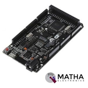
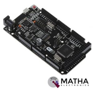
Mega R3 +WiFi ATmega2560+ESP8266 Module CH340G Compatible For Arduino Mega
- Microcontroller:ATmega2560
- IC Wi-Fi : ESP8266
- USB-TTL converter: CH340G
- Power Out: 5V-800mA
- Power Input USB: 5V (500mA max.)
- Power Input VIN/DC Jack: 9-24V
- Power Consumption: 5V 800mA
- Logic Level: 5V
- Wi-Fi 802.11 b/g/n 2.4 GHz
- USB: Micro USB
- Clock Frequency: 16MHz
- Operating Supply Voltage: 5V
- Digital I/O: 54
- Analog I/O: 16
- Memory Size: 256kb
- Data RAM Type/Size: 8Kb
- Data ROM Type/Size: 4Kb
- Interface Type: SerialOTA
- Operating temperature:−40С°/+125С°
- Build in external antenna
- Dimensions:53.361×101.86mm

NUCLEO-64 STM32G071RBT6 Development Board Arduino & ST Morpho Connectivity
- STM32 microcontroller in LQFP64 package
- 1 user LED shared with ARDUINO®
- 1 user and 1 reset push-buttons
- 768 kHz crystal oscillator
- Board connectors: ARDUINO Uno V3 expansion connectors morpho extension pin headers for full access to all STM32 I/Os
- Flexible power-supply options: ST-LINK, USB VBUS, or external sources
- On-board ST-LINK debugger/programmer with USB re-enumeration capability: mass storage, Virtual COM port and debug port
- Comprehensive free software libraries and examples available with the STM32Cube MCU Package
- Support of a wide choice of Integrated Development Environments (IDEs) including IAR Embedded Workbench®, MDK-ARM, and STM32CubeIDE
- Board-specific features
- External SMPS to generate Vcore logic supply
- 24 MHz HSE
- Board connectors: External SMPS experimentation dedicated connector Micro-AB or Mini-AB USB connector for the ST-LINKMIPI® debug connector
- Arm® Mbed Enabled™ compliant



Sensor Shield V5 Expansion Board For Arduino
- Retain the merits of the V4.0 version
- Laminated design
- PCB immersion gold processing technology
- IIC interface
- Bluetooth module communication interface
- SD card module communication interface
- APC220 Wireless RF modules communication interface
- RB URF v1.1 ultrasonic sensors interface
- 12864 LCD string of line and parallel interface
- 32 servo controller interface
Reviews
There are no reviews yet.