
I am text block. Click edit button to change this text. Lorem ipsum dolor sit amet, consectetur adipiscing elit. Ut elit tellus, luctus nec ullamcorper mattis, pulvinar dapibus leo.
-20%


RFID 13.56MHz Card
Original price was: ₹45.00.₹35.00Current price is: ₹35.00. inc. GST
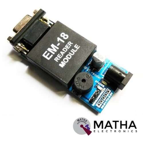
RFID EM18 125KHz RS232 Output
Original price was: ₹600.00.₹500.00Current price is: ₹500.00. inc. GST
SIM800A Quadband GSM / GPRS Module convertible as Shield for Arduino
Original price was: ₹1,500.00.₹1,200.00Current price is: ₹1,200.00. inc. GST
- Quad-Band GSM/GPRS 850/ 900/ 1800/ 1900 MHz.
- GPRS class 2/10.
- Input Voltage: 9V-12V DC.
- Control via AT commands (3GPP TS 27.007, 27.005 and SIMCOM enhanced AT command set).
- Configurable baud rate.
- Built-in SIM Cardholder.
- Built-in Network Status LED.
- 5V interface for direct communication with MCU kit.
- Inbuilt Powerful TCP/IP protocol stack for internet data transfer over GPRS.
- Low power.
- SMA connector with GSM L Type Antenna.
- Headphone jack for audio out.
- Li-Po battery 3.7-volt pins for supply.
- Li-Po battery USB charger (3.7volts).
- CP2102 port for communication with a laptop.
Description
This module designed with SIMCOM Makes the SIM800 Quad-band GSM/GPRS engine, which operates on frequencies 850 MHz, 900 MHz, 1800 MHz, and 1900 MHz. This small size and easy to use as a plug-in GSM Modem. Using the AT command the baud rate is configurable from 9600-115200. And it can transmit Voice, SMS, and data information with low power consumption. Firstly the Modem is in Auto baud mode. Hence the modem needs only two wires (Tx, Rx) except the Power supply to interface with the microcontroller/Host.
The SIM800A Quad-Band GSM/GPRS Module with RS232 Interface is a complete Quad-band GSM/GPRS solution in an LGA(Land grid array) type which can be embedded in the customer applications. It measures 100 x 53 x 15 mm, which can easily fit into the slim and compact demands of custom design.
Moreover, this SIM800A modem built with SIM800A GSM chip and RS232 interface ensures easy connection with the computer or laptop. This was achieved using the USB to the Serial connector or to the microcontroller using the RS232 to TTL converter. Once the SIM800A modem is connected using the USB to RS232 connector, the correct COM port from the Device Manager of the USB to Serial Adapter should be identified.
After that, you can open Putty or any other terminal software. Thereafter, open a connection to that COM port at 9600 baud rate, which is the default baud rate of this modem. Once a serial connection is open through the computer or your microcontroller, start sending the AT commands. When an AT command is sent for example “or” you should receive back a reply from the SIM800A modem saying “OK” or other response depending on the command sent.
Application :
- Remote POS (point of sale) terminals.
- Traffic signals monitor and control.
- Fleet management.
- Power distribution network supervision.
- Central heating system supervision.
- The weather station data transmission.
- Hydro-logic data acquisition.
- Vending machine.
Reviews (0)
Shipping & Delivery

Related products


2.4″ Inch Touch Screen TFT Display Shield for Arduino
- 4″ Touch LCD TFT display module for Arduino
- 240*320 pixels resolution
- Ability to display 262000 different colours
- The shield comes equipped with a microSD card slot.
- SPFD5408 controller with built-in video RAM buffer
- 8-bit digital interface, plus 4 control lines
- 5V compatible. Use with 3.3V or 5V logic
- On-board 3.3V 300mA LDO regulator
- Uses digital pins 5-13 and analogue 0-3. That means you can use digital pins 2, 3, and analog 4 and 5. Pin 12 is available if not using the microSD
- Works with any Arduino Uno and mega compatible boards
- Resolution: 240320 pixels
- Supply voltage: 5V
- Working temperature: -30C ~ 70C
- Dimension: 72*52*12mm
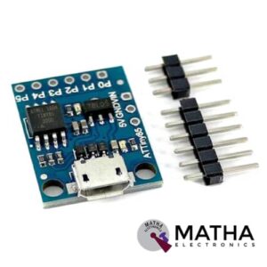

ATtiny85 Arduino-enabled Mini USB Dev Board
- Support for the Arduino IDE 1.0+ (OSX/Win/Linux)
- Power via USB or External Source
- Onboard 5V Regulator
- Built-in USB
- 6 I/O Pins
- 8k Flash Memory (about 6k after bootloader)
- I2C and SPI (vis USI)
- PWM on 3 pins (more possible with Software PWM)
- 10-bit ADC
- ADC on 4 pins
- Power LED and Test/Status LED
- Low Power Consumption
- Active Mode:1 MHz, 1.8V: 300 µA


CAN Bus Shield
- Implements CAN V2.0B at up to 1 Mb/s
- Industrial standard 9 pin sub-D connector
- OBD-II and CAN standard pinout selectable.
- Changeable chip select pin
- Changeable CS pin for TF card slot
- Changeable INT pin
- Screw terminal that easily to connect CAN_H and CAN_L
- Arduino Uno pin headers
- Grove connectors (I2C and UART)
- SPI Interface up to 10 MHz
- Standard (11 bit) and extended (29 bit) data and remote frames
- Two receive buffers with prioritized message storage


L293D Motor Driver Shield
- L293D motor driver chip & 74HC595 shift register
- Four H-bridges
- Terminal blocks and jumper to connect external power, for separate logic/motor supplies
- Up to 4 bi-directional DC motors with individual 8-bit speed selection
- Up to 2 stepper motors (unipolar or bipolar) with single coil, double coil or interleaved stepping.
- 2 connections for 5V ‘hobby’ servos connected to the Arduino’s high-resolution dedicated timer
- 4 H-Bridges: L293D chipset provides 0.6A per bridge (1.2A peak) with thermal shutdown protection, internal kickback protection diodes. Can run motors on 4.5VDC to 25VDC.
- Pull-down resistors keep motors disabled during power-up
- Big terminal block connectors to easily hook up wires (18-26AWG) and power
- Arduino reset button brought up top
- Tested compatible with Arduino Mega 1280 & 2560, Diecimila, Duemilanove, and UNO
- PCB Size: 69 x 53 mm

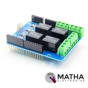
RELAY SHEILD
- Every channel maximum convert voltage: AC 125V / DC 24V
- Every channel maximum converts current: 3A
- Interface via digital I/O pins 4,5,6, and 7
- Relay screw terminals
- Standardized shield shape and design
- LED working status indicators for each relay
- High quality relays
- COM, NO (Normally Open), and NC (Normally Closed) relay pins for each relay
- Update pin SCL, SDA, IOREF, NC.
- Arduino,Crowduino,Seeeduino,Arduino Mega compatible
- Automatic control and manual control
- 4 mechanical relays with photo-coupled circuit
- 3-M3 screw hole easy to install
- Driven by 5V / 3.3V normally open contact close
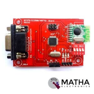
Zigbee CC2500 RS232
- RS-232 direct interface
- TTL support
- RSSI value between two modules can be obtained
- Separate LED for RX, TX, and power
- 4-bit channel selection
- Programmable output power
- Automatic packet processing
- 6 data pipes for 1:6 star networks
- 4-pin SPI interface with maximum 8 MHz clock rate 7
- 20-pin 4x4mm QFN package
Reviews
There are no reviews yet.