
I am text block. Click edit button to change this text. Lorem ipsum dolor sit amet, consectetur adipiscing elit. Ut elit tellus, luctus nec ullamcorper mattis, pulvinar dapibus leo.
-2%Sold out


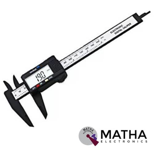
150mm 6 inch LCD Digital Electronic Vernier Caliper
Original price was: ₹900.00.₹850.00Current price is: ₹850.00. inc. GST
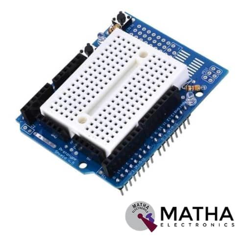
Protosheild For Arduino
Original price was: ₹355.00.₹250.00Current price is: ₹250.00. inc. GST
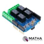
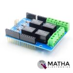
RELAY SHEILD
Original price was: ₹510.00.₹499.00Current price is: ₹499.00. inc. GST
- Every channel maximum convert voltage: AC 125V / DC 24V
- Every channel maximum converts current: 3A
- Interface via digital I/O pins 4,5,6, and 7
- Relay screw terminals
- Standardized shield shape and design
- LED working status indicators for each relay
- High quality relays
- COM, NO (Normally Open), and NC (Normally Closed) relay pins for each relay
- Update pin SCL, SDA, IOREF, NC.
- Arduino,Crowduino,Seeeduino,Arduino Mega compatible
- Automatic control and manual control
- 4 mechanical relays with photo-coupled circuit
- 3-M3 screw hole easy to install
- Driven by 5V / 3.3V normally open contact close
Out of stock
Description
The Relay Shield is designed as an Arduino compatible smart module with 4 mechanical relays. This is a simpler and easier way to control high voltage with maximum switching power of 35VDC 70W for each channel. This Relay Shield module is controlled directly by Arduino/Crowduino through digital IOs with an external 6.5 to 12V DC supply. The 4 onboard control keys used to control the high voltage without programming. It features four high-quality relays and provides NO/NC interfaces. And four dynamic LED indicators to show the on/off state of each relay. And the standardized shield form factor to provide a smooth connection to the Arduino/Seeeduino board or other Arduino compatible boards.
The Relays are basically electromagnetic switches in which the relay is energized by the control circuit. When a voltage and current are applied to the coil, the current and coil create a magnetic field. As a result, it attracts the COM terminal towards the NO terminal. When the applied voltage and current are removed from the control circuit, the COM terminal returns to contact the NC terminal due to a mechanical force (usually a spring). The two “Control Circuit” terminals for each of four relays are controlled by only one Arduino Digital I/O pin. The Pins 4, 5, 6, and 7 control relays 4, 3, 2, and 1 respectively. These relay shields are used to control high voltage using low voltage, motor control, remote control, anti-hearing alarm, automatic temperature alarm, incubators, and so on.
Note: The pins on the Shield should not touch the USB connector of Arduino UNO when they are connected.
J1 Interface/Terminal Pin Description:
- COM1 (Common Pin): The relay pin is controlled from the digital pin.
- NC1 (Normally Closed): This terminal is connected to COM1 when the RELAY1 control pin (Digital 7 I/O pin) is set to low and disconnected when the RELAY1 control pin set to high.
- NO1 (Normally Open): This terminal connected to COM1 when the RELAY1 control pin (Digital 7 I/O pin)set to high and disconnected when the RELAY1 control pin set to low.
Terminals J2-4 are similar to J1 except that they control RELAY2-RELAY4 respectively.
Reviews (0)
Shipping & Delivery

Related products

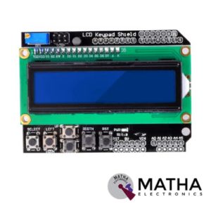
16×2 (1602) LCD Keypad Shield
- Operating Voltage:5V
- 5 Push buttons.
- RST button to reset Arduino program.
- Integrate a potentiometer for adjusting the backlight.
- Expanded available I/O pins.
- Blue light with white characters.
- Uses 4 Bit Arduino LCD Library
- Screen contrast adjustment
- Arduino Reset button
- The keypad consists of 6 keys select, up, right, down, left and reset.
- To save the digital IO pins, the keypad interface only uses one ADC channel.
- The key value is read out through a 5 stage voltage divider.


4 Channel 5V Relay Module Shield For Arduino
- Product Type: 4-Channel relay module
- Dimensions: 75 mm x 55 mm x 19.3 mm
- Weight: 61 g
- Relay colour: Blue
- PCB colour: Blue
- Maximum output of relay: AC250V 10A and Dc30V 10A
- Number of Relays: 4
- Control signal type: TTL level
- Input voltage: 5v
- Compatible with: Arduino, AVR, PIC, ARM, Raspberry Pi etc
- Package contains: 1 piece of 4 channel relay module
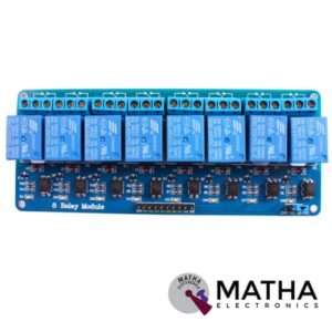
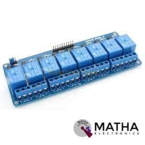
8 CHANNEL 5V RELAY
- Relay operating voltage: 5V
- 8 channel
- High impedance controller pin
- One normally closed contact and one normally opened
- Useful for appliances control
- Power supply indicator and control indicator lamp
- Pull-down circuit to avoid malfunction
- Can control both DC and AC to 220v AC load
- Works with both 3.3 V and 5 V logic with the less current drive
- 3 terminals per SPDT relay
- Standard interface can be directly controlled by a microcontroller like Arduino, 8051, AVR, PIC, DSP, ARM, MSP430, TTL logic
- Dimension: 7*6.4*1 inch


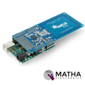

PN532 NFC/RFID Controller Shield for Arduino
- PN532 chip-set
- Operating Voltage : 3.3V ~ 5v
- Support I2C, SPI
- I2C: 3.3V ~ 24V TTL
- SPI: 3.3V TTL with 100-ohm resistors in series
- Plug and play, Arduino compatible
- Built-in PCB Antenna
- Communication distance:10cm
- Easy to change mode
- NFC/RFID PN532 shield including a tuned 13.56MHz stripline antenna
- 36-pin 0.1" header for attaching the shield to an Arduino.
- Compatible with Arduino Mega 1280 & 2560, Diecimila, Duemilanove, and UNO
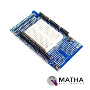

Prototype Shield V3.0 For Arduino Mega with breadboard
- The shield can support being fully assembled with Arduino MEGA
- Support soldering components directly on this shield
- Support sticking the mini breadboards on this shield
- Reset button up top
- Mainboard aureate quadrate
- With SOP28 SMT components encapsulation
- With PWR & STAT indicator
- Breadboard Points : 170
- Shield Size (mm) : 102×56
- Breadboard Size (mm) : 48×34
- Weight (gm) :35


Screw Shield Expansion board for Arduino
- Arduino terminal to provide the IO, port connection.
- 81 posts quality, reliable, convenient, durable.
- Combined with the Proto Shield, the middle can be used as a prototype expansion board.
- Double-sided PCB Prototyping extended area vias connecting the front sides can be welded components.
- The middle section can be placed small bread plate, convenient test extend


Sensor Shield V5 Expansion Board For Arduino
- Retain the merits of the V4.0 version
- Laminated design
- PCB immersion gold processing technology
- IIC interface
- Bluetooth module communication interface
- SD card module communication interface
- APC220 Wireless RF modules communication interface
- RB URF v1.1 ultrasonic sensors interface
- 12864 LCD string of line and parallel interface
- 32 servo controller interface
Reviews
There are no reviews yet.