
I am text block. Click edit button to change this text. Lorem ipsum dolor sit amet, consectetur adipiscing elit. Ut elit tellus, luctus nec ullamcorper mattis, pulvinar dapibus leo.
-8%

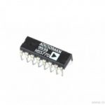
ADG509 4-Channel Analog Multiplexer IC
Original price was: ₹210.00.₹200.00Current price is: ₹200.00. inc. GST
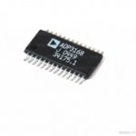
ADP3168 6-Bit, Programmable 2-, 3-, 4-Phase Synchronous Buck Controller IC
Original price was: ₹65.00.₹55.00Current price is: ₹55.00. inc. GST
74279N Quadruple S-R Latch IC
Original price was: ₹60.00.₹55.00Current price is: ₹55.00. inc. GST
- Quadruple S-R Latch
- High-level output voltage: 3.4V
- Low-level output voltage: 0.2V
- High-level output current: -0.8mA
- Low-level output current: 16mA
- Input clamp voltage: -1.5V
- Propagation delay time max: 27ns
- Supply voltage range: 4.75 to 5.25V
- Package: DIP-16
Description
The 74279 designed with 4 individual and independent Set-Reset Latches with active-low inputs. Two of the
four latches have a further S input ANDed with the first S input. A Low on any S input while the R input is
HIGH stored within the latch and appear on the corresponding Q output as a HIGH. Whereas the Low on the R input, while the S input is HIGH, will clear the Q output to a low. Meanwhile, the Q output is uncertain due to the simultaneous transition of the R and S inputs from LOW to HIGH. Both inputs are voltage level triggered and do not suffer from the input data transition delay.
The 74C279 designed as a high-speed CMOS QUAD S- R LATCH fabricated in silicon gate C2MOS technology. It offers the same high-speed performance of LSTTL combined with true CMOS low power consumption. Moreover, all inputs are equipped with protection circuits against static discharge and transient excess voltage.
Logic gates are used to make flip flops. A flip-flop circuit can stay in a binary state indefinitely (as long as power is supplied) unless prompted to change states by an input. SET-RESET flip-flops are also known as S-R flip-flops. Two NOR gates and two NAND gates make up the SET-RESET flip-flop. S-R Latch is another name for these flip-flops. The SET [S] and RESET [R] inputs are also included in the design of those flip flops. There are two outputs as well, Q and Q’.
Reviews (0)
Shipping & Delivery

Related products

10 Segment Led Bargraph Light Display Red, Yellow, Green, Blue
- LED type: LED array bar
- Segments: 10
- LED Colour: Green
- Housing color: white
- Reverse voltage: 5V
- Forward Voltage - Typical: 1.85 V
- Forward Voltage - Maximum: 2.2 V
- DC forward current: 30mA
- Peak forward current: 175mA
- Power dissipation: 75mW
- Peak wavelength: 590nm
- Luminous Intensity Typical: 120 Mcd
- Operating temperature: -40°C to +85°C
- 10 Separately Controlled LED's
- High Brightness
- High-Intensity Green Output
- Ideal for Audio and Meter Displays
- Economically priced
- Easy to Mount
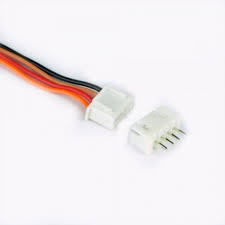
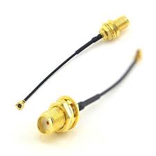

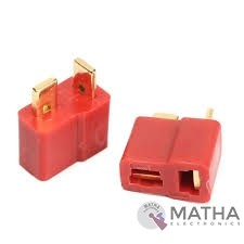
Dean Connector
- Male plug size: About 13* 7* 19mm
- Female plug size: About 13* 7* 15mm
- Current Rating: 30Amps
- Colour: Red and golden
- Material: Plastic and metal
- Provides a secure connection for battery and motor connections
- Eliminates the possibility of wrong polarity connections
- Used in RC hobby, car, boat, plane, helicopter, LIPO battery, etc.
- Dimension: 9x0.7x2cm
- Weight:20gm


Dual Micro USB 3.7v to 5V 2A Power Bank DIY 18650 LiPo Charger
- 4-level LED lamp display power, not working state intelligent automatic shutdown;
- The built-in lithium battery protection IC, over-current, under-voltage protection;
- Dual USB output ports.
- Dimensions: 68 x 34 x 9 mm (LxWxH)
- Weight: 10 gm
- Input port: MicroUSB (Andro)
- Input requirements: 5V constant voltage power supply can do charge input power, the most matching charger for 5v1a above
- Output port: USB
- Output parameters: 5V1A/5V2A
- Requirements for rechargeable batteries:
- Compatible Batteries: 18650 batteries, cell phone batteries, flat-panel batteries, MP3 batteries, etc. 3.7v-4.2V polymer Lithium battery,

GSM Antenna Dlenp 2dbi/3dbi Patch Antenna with SMA Male Connector
- GSM Antenna
- Gain: 2 to 3dbi
- Wire Length: 3 metre
- 3dbi Sticker Antenna
- GSM Antenna
- SMA Male Connector
- Frequency Range(MHz): 824-960/1710-1990Mhz
- Bandwidth (MHz): 136/280
- VSWR≤1.5
- Gain(dB): 2-3dbi
- Max Input power(W): 60W
- Input Impedance: 50 Ω
- Polarization Type: Vertical
- Cable Type: RG174
- Mounting Adhesive
- Net weight: 47g

HX711–24 Bit Analog to Digital Converter (ADC)
- It is an ADC converter with two differential input channels
- An active-low noise PGA is integrated inside the chip which provides the gain of 32, 64 and 128
- It has a power-on-reset capability which simplifies digital interface initialization.
- All controls to the IC are made through the pins. Programming is not needed.
- You can select a data rate of 10SPS or 80SPS at the output.
- Provides simultaneous supply rejection of 50Hz and 60Hz supply.
- Built-in analog power supply regulator
- The voltage supply range is from 2.6V to 5.5V
- The temperature range is from -40 °C to +85℃
Reviews
There are no reviews yet.