
I am text block. Click edit button to change this text. Lorem ipsum dolor sit amet, consectetur adipiscing elit. Ut elit tellus, luctus nec ullamcorper mattis, pulvinar dapibus leo.

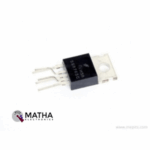
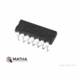
IRS2110 High and Low Side Driver IC
- High Side Floating Supply Voltage Max.: 520V
- Logic 1 input voltage Min.: 9.5V
- Logic 0 input voltage Max.: 6V
- High level output voltage Max.: 1.2V
- Low level output voltage Max.: 0.15V
- Total Power Dissipation: 1.6W
- Propagation delay Max.: 160ns
- Rise Time Max.: 35ns
- Fall Time Max.: 25ns
- Package: DIP-14
Description
The IR2110 designed as a self-oscillating high voltage, high-speed power MOSFET and IGBT driver comprises of dependent high and low side referenced output channels designed explicitly for half-bridge applications. Proprietary HVIC and latch immune CMOS technologies enable ruggedized monolithic construction. The front end features a programmable oscillator which is similar to the 555 timer. Logic inputs are compatible with standard CMOS or LSTTL output, down to 3.3V logic.
The output drivers provide a high pulse current buffer stage designed for minimum driver cross-conduction. Internal deadtime employed to avoid shoot-through in the output half-bridge. Propagation delays are matched to simplify use in high-frequency applications. The floating channel used to drive an N-channel power MOSFET/IGBT in high side configuration which operates up to 500 or 600 volts. Meanwhile, it offers a Gate drive supply voltage at a range from 10 to 20V. Moreover, this gate driver IC features an Undervoltage lockout for both channels. IR2110 Half-Bridge Driver IC manufactured in 14pin-Lead PDIP or 8-Lead SOIC package.
The Half-Bridge Driver IC employed to drive the gates of high- and low-side N-channel MOSFETs (or IGBTs) with a low output impedance to reduce the conduction losses, and a fast switching time to reduce the switching losses. The high-and low-side drivers requires very close matching of the timing characteristics. Thus allow accurate and efficient switching of the device. This minimises the deadtime from one switch of the half-bridge turning off before the second switch turns on. Isolated half-bridge gate drivers+ widely utilized in many applications that range from isolated dc-to-dc power supply modules where high power density and efficiency are necessary, to solar inverters where high isolation voltage and long-term reliability are mandatory.
Reviews (0)
Shipping & Delivery

Related products


1/4W 5% Assorted Value Carbon Film Resistor Assortment Kit Set pack electronic diy kit
- 100% brand new and high quality.
- Fine workmanship and long service life.
- 1/4W carbon film resistor package.
- High precision and stability.
- Easy to use.
- Precision: 5%
- Error: 5%
- Values
- 10Ω, 15Ω, 22Ω, 33Ω, 47Ω, 68Ω, 100Ω, 220Ω, 330Ω, 470Ω, 1k, 1k5, 2k2, 3k3, 4k7, 5k6, 6K8, 8K2, 10K, 15K, 22K, 33K, 47K, 56K, 68K, 100K, 150K, 220K, 330K, 470K
- Package included: 150pcs

25pcs Button Switch Kit
- Relative Humidity: 95%
- Rated Voltage: 12V
- Rated Current: 50 mA
- Contact resistance: 50M Ohm Max (initial)
- The insulation resistance: 100M Ohm minDC (250V)
- The compressive strength: AC250V (50/60Hz for 1 minute)
- Mechanical life: 100000 cycles
- The environment temperature: 25° ~ + 105°
- The operating strength: 180/250 (plus or minus 30gf)
- Dimension: 12 * 12 * 7.3 round convex type
- Total Buttons: 25pcs
- Colours: 5 (Black, Red, White, Blue, Yellow)

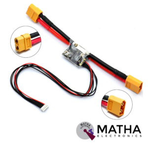
APM/Pixhawk Power Module V6.0 Output BEC 3A XT60 Plug 28V 90A
- Input Voltage Range: 6-28V DC
- Output voltage: 5.3V ± 0.1V
- Maximum output current: 3A
- Maximum current: 90A
- Maximum voltage: 30V
- Supports from 2 cell to 6 cell battery.
- 6P cable can be directly connected to APM/Pixhawk flight control
- Additional 4P rows of pin-free to wire/PIN to connect to another flight control
- Voltage and current measurement configured for 5V ADC.
- Switching regulator outputs 5.3V and 3A max.
- Dimensions: 25mm x 21mm x 9mm
- Weight: 17gm


Dual Micro USB 3.7v to 5V 2A Power Bank DIY 18650 LiPo Charger
- 4-level LED lamp display power, not working state intelligent automatic shutdown;
- The built-in lithium battery protection IC, over-current, under-voltage protection;
- Dual USB output ports.
- Dimensions: 68 x 34 x 9 mm (LxWxH)
- Weight: 10 gm
- Input port: MicroUSB (Andro)
- Input requirements: 5V constant voltage power supply can do charge input power, the most matching charger for 5v1a above
- Output port: USB
- Output parameters: 5V1A/5V2A
- Requirements for rechargeable batteries:
- Compatible Batteries: 18650 batteries, cell phone batteries, flat-panel batteries, MP3 batteries, etc. 3.7v-4.2V polymer Lithium battery,
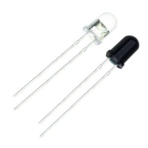
IR LED Sensor
- Size: 5mm LED
- Wavelength: 940nm wavelength (most commonly used)
- Forward current (IF) is 100mA (normal condition) and 300mA (max.)
- 5A of surge forward current
- 24v to 1.4v of forward voltage
- Temperature : -40 to 100 ℃
- Soldering Temperature should not exceed 260 ℃
- Power Dissipation of 150mW at 25℃ (free-air temperature) or below
- Spectral bandwidth of 45nm
- Viewing angle: 30 to 40 degree
- High Reliability
- Excessive radiant intensity
- Having lead spacing of 2.54mm
- Easy to use with breadboard or perf board
Reviews
There are no reviews yet.