
I am text block. Click edit button to change this text. Lorem ipsum dolor sit amet, consectetur adipiscing elit. Ut elit tellus, luctus nec ullamcorper mattis, pulvinar dapibus leo.


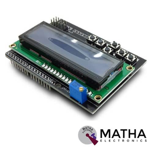
16x2 (1602) LCD Keypad Shield
Original price was: ₹450.00.₹400.00Current price is: ₹400.00. inc. GST
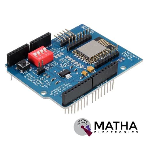
ESP8266 WIFI Shield
Original price was: ₹935.00.₹899.00Current price is: ₹899.00. inc. GST
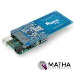
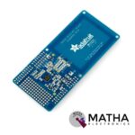
PN532 NFC/RFID Controller Shield for Arduino
₹1,500.00 inc. GST
- PN532 chip-set
- Operating Voltage : 3.3V ~ 5v
- Support I2C, SPI
- I2C: 3.3V ~ 24V TTL
- SPI: 3.3V TTL with 100-ohm resistors in series
- Plug and play, Arduino compatible
- Built-in PCB Antenna
- Communication distance:10cm
- Easy to change mode
- NFC/RFID PN532 shield including a tuned 13.56MHz stripline antenna
- 36-pin 0.1″ header for attaching the shield to an Arduino.
- Compatible with Arduino Mega 1280 & 2560, Diecimila, Duemilanove, and UNO
Description
NFC/RFID Sheild was designed as a perfect tool for any 13.56MHz RFID or NFC application. This NFC shield uses the PN532 chip set. PN532 NFC Module was designed as a highly integrated radio transmission module for Near Field Communication at 13.56MHz. NFC protocol designed for smartphones and similar devices, can read and write cards and tags, interact with NFC phones, and enable communication from device to device. While the controller provides many capabilities. Our Arduino library currently only supports reading/writing tags and does not support phone-to-shield communication, tag emulation (which requires an external ‘secure element’ only available from NXP) or other more advanced features at this time.
This shield comes with a tuned 13.56MHz stripline antenna, 36-pin 0.1″ header for attaching the shield to an Arduino. In order to stack another shield on top or below, stacking headers allow pass-through stacking. This shield was designed by RF engineers using the best test equipment to create a layout. And antenna within a range of 10cm (4 inches), the maximum range possible using the 13.56MHz technology. It is quite easy to attach the shield behind a plastic plate with standoffs and still read cards through a (non-metal) barrier.
This shield supports I2C or SPI communication protocols. I2C is the default, as it uses fewer pins. Analog pins 4 and 5 are used for I2C ( you can still connect other I2C devices to the bus). And Digital #2 is used for “interrupt” notification. This means we don’t have to sit there and ‘poll’ the chip to ask a target tag has been found. The pin will pull low when a card, phone, etc is within range. The shield changes over to SPI easily where you can use any 4 digital pins by shorting two solder jumpers on the top of the PCB. These NFC/RFID Compatible with any “classic” Arduino – NG, Diecimilla, Duemilanove, UNO – as well as Mega R3 or later.
Reviews (0)
Shipping & Delivery

Related products

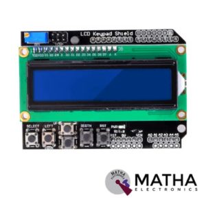
16×2 (1602) LCD Keypad Shield
- Operating Voltage:5V
- 5 Push buttons.
- RST button to reset Arduino program.
- Integrate a potentiometer for adjusting the backlight.
- Expanded available I/O pins.
- Blue light with white characters.
- Uses 4 Bit Arduino LCD Library
- Screen contrast adjustment
- Arduino Reset button
- The keypad consists of 6 keys select, up, right, down, left and reset.
- To save the digital IO pins, the keypad interface only uses one ADC channel.
- The key value is read out through a 5 stage voltage divider.

4*4 MATRIX KEYPAD
The maximum voltage across each button: 24v
- The maximum current across each button: 3mA
- Easy communication with any microcontroller
- Ultra-thin design
- Adhesive backing provides easy integration
- High price-performance ratio
- Allows microcontroller to scan 8 output pins to check which 16 button
- Long life
- Maximum operating temperature: 0 degrees to 50 degrees Celsius
- Dimension: 70*77*1mm
- Weight: 7.5gm
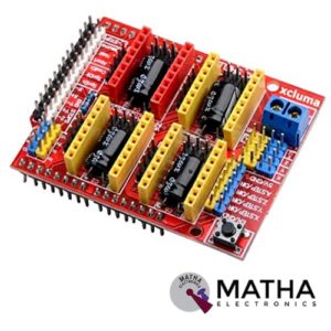

Arduino CNC Shield v3 Engraving Machine/3D Printer/A4988 driver GRBL compatible
- Coolant enable
- Uses removable Pololu A4988 compatible stepper drivers. (A4988, DRV8825, and others) (Not Included)
- Jumpers to set the Micro-Stepping for the stepper drivers. (Some drivers like the DRV8825 can do up to 1/32 micro-stepping )
- Compact design.
- Stepper Motors can be connected with 4 pin Molex connectors or soldered in place.
- Runs on 12-36V DC. (At the moment only the Pololu DRV8825 drivers can handle up to 36V so please consider the operation voltage when powering the board.)
- Please note that this is an unassembled kit and needs soldering.
- Latest Arduino CNC Shield Version 3.10
- GRBL 0.9 compatible. (Open source firmware that runs on an Arduino UNO that turns G-code commands into stepper signals)
- PWM Spindle and direction pins
- 4-Axis support (X, Y, Z, A-Can duplicate X, Y, Z or do a full 4th axis with custom firmware using pins D12 and D13)
- 2 x End stops for each axis (6 in total)
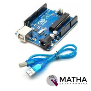

Arduino Duemilanove Development Board with USB Cable
- Microcontroller: ATmega168/ATmega 328
- Operating Voltage: 5V
- Input Voltage: 7-12V
- Input Voltage: 6-20V
- Digital I/O Pins: 14 (of which 6 provide PWM output)
- Analog Input Pins: 6
- DC Current per I/O Pin: 40 mA
- DC Current for 3.3V Pin: 50 mA
- Flash Memory: 16 KB (ATmega168) or 32 KB (ATmega328) of which 2 KB used by the bootloader
- SRAM: 1 KB (ATmega168) or 2 KB (ATmega328)
- EEPROM: 512 bytes (ATmega168) or 1 KB (ATmega328)
- Clock Speed: 16 MHz


CAN Bus Shield
- Implements CAN V2.0B at up to 1 Mb/s
- Industrial standard 9 pin sub-D connector
- OBD-II and CAN standard pinout selectable.
- Changeable chip select pin
- Changeable CS pin for TF card slot
- Changeable INT pin
- Screw terminal that easily to connect CAN_H and CAN_L
- Arduino Uno pin headers
- Grove connectors (I2C and UART)
- SPI Interface up to 10 MHz
- Standard (11 bit) and extended (29 bit) data and remote frames
- Two receive buffers with prioritized message storage


ESP8266 WIFI Shield
- Operating voltage 5V (supplied from the Arduino Board)
- Connection via: 802.11b/g networks
- Encryption types: WEP and WPA2 Personal
- Connection with Arduino on SPI port
- on-board micro SD slot
- ICSP headers
- FTDI connection for serial debugging of WiFi shield
- Mini-USB for updating WiFi shield firmware
- 32-bit RISC architecture
- The processor can operate at 80MHz / 160MHz
- 32MB flash memory
- 64kB for instructions
- 96kB for data
- Operates in AP, Station or AP + Station mode
- It has 11 digital pins
- It has 1 analogue pin with 10-bit resolution
- Digital pins except the D0 have interrupts, PWM, I2C and one wire
- Programmable through USB or WiFi (OTA)
- Compatible with Arduino IDE
- Compatible with modules and sensors used in Arduino

NUCLEO-64 STM32G071RBT6 Development Board Arduino & ST Morpho Connectivity
- STM32 microcontroller in LQFP64 package
- 1 user LED shared with ARDUINO®
- 1 user and 1 reset push-buttons
- 768 kHz crystal oscillator
- Board connectors: ARDUINO Uno V3 expansion connectors morpho extension pin headers for full access to all STM32 I/Os
- Flexible power-supply options: ST-LINK, USB VBUS, or external sources
- On-board ST-LINK debugger/programmer with USB re-enumeration capability: mass storage, Virtual COM port and debug port
- Comprehensive free software libraries and examples available with the STM32Cube MCU Package
- Support of a wide choice of Integrated Development Environments (IDEs) including IAR Embedded Workbench®, MDK-ARM, and STM32CubeIDE
- Board-specific features
- External SMPS to generate Vcore logic supply
- 24 MHz HSE
- Board connectors: External SMPS experimentation dedicated connector Micro-AB or Mini-AB USB connector for the ST-LINKMIPI® debug connector
- Arm® Mbed Enabled™ compliant

STM32 Nucleo-64 development board with STM32F103RB MCU, supports Arduino and ST morpho connectivity
- STM32 microcontroller with LQFP64 package
- Two types of extension resources
- mbed-enabled (mbed.org)
- On-board ST-LINK/V2-1 debugger/programmer with SWD connector
- Flexible board power supply
- Three LEDs
- Two push buttons: USER and RESET
- USB re-enumeration capability: three different interfaces supported on USB
- Comprehensive free software HAL library including a variety of software examples
- Supported by wide choice of Integrated Development Environments (IDEs) including IAR, Keil, GCC-based IDEs
Reviews
There are no reviews yet.