
I am text block. Click edit button to change this text. Lorem ipsum dolor sit amet, consectetur adipiscing elit. Ut elit tellus, luctus nec ullamcorper mattis, pulvinar dapibus leo.
-42%

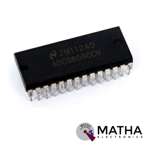
ADC0808 8-Bit A/D Converter with 8-Channel Multiplexer IC DIP-28 Package
Original price was: ₹180.00.₹140.00Current price is: ₹140.00. inc. GST
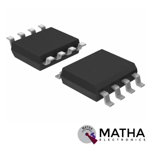
PCF8583 IC
Original price was: ₹100.00.₹65.00Current price is: ₹65.00. inc. GST
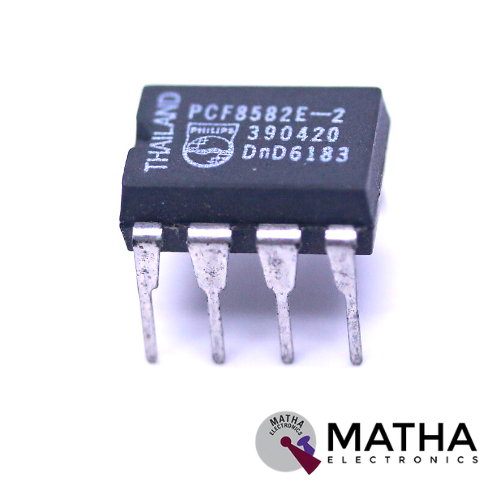
PCF8582E-2 IC DIP-8
Original price was: ₹60.00.₹35.00Current price is: ₹35.00. inc. GST
- Low power CMOS
- Non-volatile storage of 2 kbits organized as 256 × 8-bit
- Single supply with full operation down to 2.5 V
- On-chip voltage multiplier
- Serial input/output I2C-bus
- Write operations:
- – byte write mode
– 8-byte page write mode (minimizes total write time per byte)
- Read operations:
– sequential read
– random read
- Internal timer for writing (no external components)
- Internal power-on reset
- 0 kHz to 100 kHz clock frequency
- High reliability by using a redundant storage code
Description
The PCF8582 is a 256×8 CMOS EEPROM with an I2C interface. It comes in a range of plastic 8- and 16-pin units. The 16-pin Dual In-Line package is utilized in this specific arrangement. A 128×8 CMOS EEPROM, PCF8581. Philips television sets that utilize I2C EEPROMs can have their default setup parameters programmed with this Gang Programmer. In addition to demonstrating how to build an I2C interfaced programmer, the design is offered here as an illustration of how to use the 87C751 I2C interface. The data is copied into ten slave EEPROMs by the programmer after being read from a source EEPROM.
The programmer is powered by a 9V @ 300mA wall-mounted source. On the board, there is a 5V regulator. A yellow LED is used to show that the board has received power. There are red LEDs at each socket to signal a failure in the programming procedure for that IC, and green and pink LEDs to indicate the status of the programming operation. If everything goes according to plan, a buzzer will sound and a green LED will show that the programming procedure was successful. If there are any EEPROM faults, the pink LED will illuminate, and the relevant red LED will flash to show which IC is malfunctioning. The I2C communication link has malfunctioned if the pink LED is on but none of the red LEDs are lit.
Reviews (0)
Shipping & Delivery

Related products


1/4W 5% Assorted Value Carbon Film Resistor Assortment Kit Set pack electronic diy kit
- 100% brand new and high quality.
- Fine workmanship and long service life.
- 1/4W carbon film resistor package.
- High precision and stability.
- Easy to use.
- Precision: 5%
- Error: 5%
- Values
- 10Ω, 15Ω, 22Ω, 33Ω, 47Ω, 68Ω, 100Ω, 220Ω, 330Ω, 470Ω, 1k, 1k5, 2k2, 3k3, 4k7, 5k6, 6K8, 8K2, 10K, 15K, 22K, 33K, 47K, 56K, 68K, 100K, 150K, 220K, 330K, 470K
- Package included: 150pcs

10 Segment Led Bargraph Light Display Red, Yellow, Green, Blue
- LED type: LED array bar
- Segments: 10
- LED Colour: Green
- Housing color: white
- Reverse voltage: 5V
- Forward Voltage - Typical: 1.85 V
- Forward Voltage - Maximum: 2.2 V
- DC forward current: 30mA
- Peak forward current: 175mA
- Power dissipation: 75mW
- Peak wavelength: 590nm
- Luminous Intensity Typical: 120 Mcd
- Operating temperature: -40°C to +85°C
- 10 Separately Controlled LED's
- High Brightness
- High-Intensity Green Output
- Ideal for Audio and Meter Displays
- Economically priced
- Easy to Mount


ADXL 335 Accelerometer IC
- 3-axis sensing
- Small, low profile package
- 4 mm × 4 mm × 1.45 mm LFCSP
- Low power : 350 μA (typical)
- Single-supply operation: 1.8 V to 3.6 V
- 10,000 g shock survival
- Excellent temperature stability
- BW adjustment with a single capacitor per axis
- RoHS/WEEE lead-free compliant
- 8V- 3.6V single-supply operation
- Integrated X, Y, and Z axis accelerometer on a single chip
- X and Y axis has a 0.5Hz to 1600Hz bandwidth
- Z axis has a 0.5Hz to 550Hz bandwidth
- Hermetically sealed for temp and humidity resistance
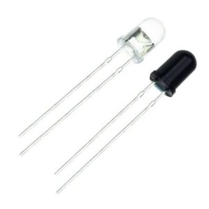
IR LED Sensor
- Size: 5mm LED
- Wavelength: 940nm wavelength (most commonly used)
- Forward current (IF) is 100mA (normal condition) and 300mA (max.)
- 5A of surge forward current
- 24v to 1.4v of forward voltage
- Temperature : -40 to 100 ℃
- Soldering Temperature should not exceed 260 ℃
- Power Dissipation of 150mW at 25℃ (free-air temperature) or below
- Spectral bandwidth of 45nm
- Viewing angle: 30 to 40 degree
- High Reliability
- Excessive radiant intensity
- Having lead spacing of 2.54mm
- Easy to use with breadboard or perf board


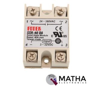
Solid State Relay Module DC To AC SSR-40DA 3-32VDC/24-380VAC 40A
- Control mode: DC-AC
- Input voltage: 3-32V DC.
- Output voltage: 24-380V AC.
- Output current: 40A.
- Working voltage: 250V.
- Material: plastic + metal.
- Loading current: 40A
- Control current: 3-25mA DC
- On voltage: ≤1.5V AC
- One-off Time: ≤10ms
- Off Leakage Current: ≤2mA
- Dielectrics voltage-resistance: 2500VAC
- Environment temperature: -30 to +75
- Long service life and high reliability.
- Reduced electromagnetic interference.
- Highly reliable, compact size designed to offer users maximum simplicity.
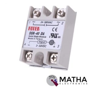

Solid State Relay SSR-40DD 40A 3-32V DC to 5-60V DC SSR 40DD Relay Solid State
- Model: SSR-40 DD.
- Control mode: DC-DC
- Input voltage: 3-32V DC.
- Output voltage: 5-60V DC.
- Output current: 40A.
- On voltage: ≤1v.
- One-off time: ≤10ms.
- Off leakage current: ≤2ma.
- Loading current: 40A
- Control current: 3-25mA DC
- Material: plastic + metal.
- Environment temperature: -30 to +75
- Long service life and high reliability.
- Reduced electromagnetic interference.
- Highly reliable, compact size designed to offer users maximum simplicity.
- Weight: 0. 106Kg.
Reviews
There are no reviews yet.