

“PWM Generator Module for Stepper Motor Driver with Forward and Reverse Function “
- Board can be used to generate PWM signals for the stepper motor driver
- Operating Voltage: 12VDC
- Three Frequency Range
- Forward and Reverse Function.
- It has three frequency ranges selectable via onboard jumpers.
- Frequency can be measured via PUL and common cathode (GND) ports.
- The board has two sets of power input
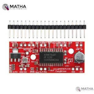
A3967 STEPPER MOTOR DRIVER
- A3967 precision micro-stepping driver
- Power supply: 7v to 30v
- Logic voltage: 5v to 3.3v
- Higher the voltage higher the torque at high speed
- Adjustable current control from 150Ma/ phase to 750ma phase
- Automatic current decay mode detection/selection
- Fast, slow, and mixed current decay modes
- Internal UVLO and thermal shutdown circuitry
- Crossover current protection
- Micro stepping resolution to full, half, quarter, and eighth steps by broken out MS1 and MS2 pins.
- Compatible with Arduino, GRBL G-Code interpreter for driving3-axis CNC machines
- Salington sink drivers used
- Compactible with 4, 6,8 wire stepper motor of any voltage

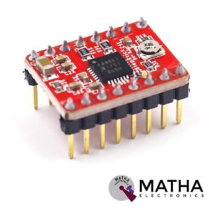
A4988 Stepper Motor
- Operating voltage supply: 8 V to 35 V
- Continuous current per phase: 1 Amp
- Maximum current per phase: 2 Amp
- Minimum logic voltage: 3V
- Maximum logic voltage: 5.5V
- Microstep resolutions: Full, 1/2, 1/4, 1/8, and 1/16
- Logic Voltage supply: 3.3 V to 5 V
- Compatible with 3V3 and 5V microcontrollers
- Our Board comes with 0.1 Ohm Sensor resistors
- Five different step resolutions: full-step, half-step, quarter-step, eighth-step, and sixteenth-step
- The Correct current decay mode (fast decay or slow decay) is selected by chopping the control
- Over-temperature thermal shutdown, under-voltage lockout, and crossover-current protection
- Short-to-ground and shorted-load protection
- 4-layer, 2 oz copper PCB for improved heat dissipation
- Exposed solderable ground pad below the driver IC on the bottom of the PCB

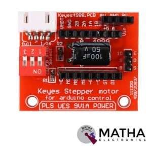
A4988 STEPPER MOTOR DRIVE CONTROLLER BOARD
- Operating voltage supply: 8 V to 35 V
- Continuous current per phase: 1 Amp
- Maximum current per phase: 2 Amp
- Minimum logic voltage: 3V
- Maximum logic voltage: 5.5V
- Microstep resolutions: Full, 1/2, 1/4, 1/8, and 1/16
- Compact size, easy to install and use.
- All jumpers hit the ON position to indicate 16 subdivisions (4988) or 32 subdivisions (8825).
- Jm connection motor; Jv Connects 5V and 12V-24V Power Supply.
- E /S /D /G of Jc corresponds to Enable /Step /Dir /Gnd driving signal output on the connection respectively.
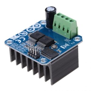
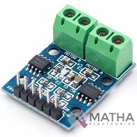
BTS7960 43A High Power Motor Driver Module/Smart Car Driver Module for Arduino Current Limit
- Input voltage: 6V-27V
- Maximum current: 43A
- Input level: 3.3-5V
- Control mode: PWM or level
- Duty cycle: 0-100%
- Double BTS7960 large current (43 A) H bridge driver
- 5V isolate with MCU and effectively protect MCU
- 5V power indicator on board
- Four lines from MCU to driver module (GND. 5V. PWM1. PWM2)
- Reverse the motor forward, two PWM input frequency up to 25kHZ
- Two heat flow passing through an error signal output
- Dimension: Approx. 4 * 5 * 1.2cm


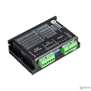
DM556 Digital Stepper Motor Driver with Micro Stepping 20 to 50V 5.6A
- Good high-speed performance
- Supply voltage: +50VDC
- Output current from 0.5A to 5.6A
- Pulse input frequency up to 200 kHz
- Extremely cost-effective
- Automatic idle-current reduction
- Self-test and Auto-configuration technology TTL compatible and optically isolated input
- Micro step resolutions programmable, from full-step to 102,400 steps/rev
- Suitable for 2-phase and 4-phase motors
- Support PUL/DIR and CW/CCW modes
- Anti-Resonance provides optimum torque and nulls mid-range instability
- Extra-low motor noise offers excellent quietness
- Over-voltage, over-current protection and phase error protection
L9110 DC Stepper Motor Driver Board H-Bridge
- Low static work current
- Power supply voltage: DC2.5-12V
- Each channel has 800mA continuous current output
- Low saturation pressure drop
- TTL/CMOS output level compatible can be connected directly to the CPU
- Output built-in clamping diode, apply to the perceptual load
- Control and drive integrated into IC
- Have pin high-pressure protection function
- Working temperature: 0-80 °C

Leadshine DM320C
- Supply voltage up to +30 VDC
- Output current programmable, from 0.3A to 2.0A
- Pulse input frequency up to 70 kHz
- TTL compatible and optically isolated input
- Automatic idle-current reduction
- Suitable for 2-phase and 4-phase motors
- Support PUL/DIR and CW/CCW modes
- Over-voltage, over-current, phase-error protection
- Anti-Resonance provides optimum torque and nulls mid-range instability
- Self-test and Auto-configuration technology offers optimum responses with different motors
- Microstep resolutions programmable, from full-step to 102,400 steps/rev
- Support PUL/DIR and CW/CCW modes
- Over-voltage, over-current, phase-error protection
- Its unique features make the DM320C an ideal solution for applications that require low-speed smoothness
Leadshine DM542
- Good high-speed performance
- Supply voltage up to +50VDC
- Output current up to 4.2A
- Pulse frequency up to 300 KHz
- Extremely cost-effective
- Automatic idle-current reduction
- 3-state current control technology
- Self-adjustment technology
- Pure-sinusoidal current control technology
- TTL compatible and optically isolated input
- 15 selectable resolutions in decimal and binary, up to 25,600 steps/rev
- Suitable for 2-phase and 4-phase motors
- DIP switch current setting with 8 different values
- Support PUL/DIR and CW/CCW modes
- Short-voltage, over-voltage, over-current protection
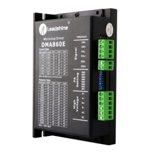
Leadshine DMA860E Stepper Motor Driver
- Model: DMA860E.
- Control Mode: Step & Direction.
- Max Input Frequency: 200 kHz.
- Input Voltage Range: 18 - 80 VAC / 24 - 110 VDC.
- Suggested Power Supply Voltage Range: 36-90 VDC /24-60 VAC.
- Number of DIP Switch Resolution Configurations: 16.
- 16 selectable micro-step resolutions of 400-51,200 via DIP switches.
- 8 selectable output current settings of 2.4 – 7.2A via DIP switches.
- Logic Current Range: 7-16mA (10mA typical).
- Logic Voltage Range: 4-5 VDC for pulse active high (default), or 0-0.5V for pulse active low.
- Pulse enabled at: Rising edge.
- Idle Current Percentage: 50 %.
- Number of Digital Inputs: 3.
- Step Width: 2,500 ns.
- Minimal Direction Setup Time: 5,000 ns.
- Isolation Resistance: 500M Ohm..
- Ambient Temperature: 0-50°C.
- Humidity: 40–95% RH.
- Operating Temperature: 0-70°C.
- Vibration: 5.9 m/s2 Max.
- Motor auto-identification and parameter auto-configuration for optimal torque from wide-range motors.
- Step & direction (PUL/DIR) and CW/CCW (via internal jumper set) control. Step & direction by default Multi-Stepping for smooth motor movement.
- Opto Isolation for input control signals.
- Soft-start with no “jump” when powered on.
- Protections for over-voltage and over-current.
- Dimension: 5.94 X 3.82 X 2.24 Inches.
- Weight: 1.13 lbs.


Leadshine DMA860H
- Input voltage: Up to +80VAC or +110VDC.
- Output current Up to 7.2A.
- Pulse input frequency up to 300 KHz.
- Automatic idle-current reduction.
- Over-voltage, over-current protection.
- Suitable for 2-phase and 4-phase motors.
- Support PUL/DIR and CW/CCW modes.
- Operating Temperature : 70 C.
- High performance, cost-effective
- Self-adjustment technology
- Pure-sinusoidal current control technology
- TTL compatible and optically isolated input
- 16 selectable resolutions in decimal and binary, up to 51,200 steps/rev

Minebea 16PU-M202 Bipolar Stepper Motor
- Step angle 3.75 degree
- Phase current: 0.6 ampere
- Step Angle: 3.75 Degree +/- 5%
- Drive Sequence: Bipolar
- Rated Current per Winding: 0.6 A
- Winding Resistance: 5E5
- Holding Torque Nm (Kg-cm): 0.064 (0.65)
- Rotor Inertia (Kg-cm2): 0.015
- Rated Voltage: Max 40V DC, 12V Typical
- Flange Size: 56.5 mm
- Shaft (with coupling spur gear): 5mm
- Connecting Wire Length: 30 cm
- Holding Torque: 0.074 nm