ANTENNA WIFI
Antenna Specifications:
- Color: Black
- Radiation: Omni-directional
- Gain:8dBi
- Frequency Range(MHz): 2400-2500, 5150-5850MHz
- Connector Type: RP-SMA Male (Hole)
- Angle Adjustable: 90° 135° 180°
- Dimension: 16cm/ 6.3”(Unbend) / 13.5cm/ 5.31”(Bend)
- Wight: 13.5g / 0.48 oz per antenna
- Color: Black & Gold
- Length: 15cm / 5.9''
- Wight:4.4g / 0.17 oz per pigtail cable
- Connector Type: U.FL/ IPEX to RP-SMA Female


ESP32MOD ESP-WROOM-32 Universal Wi-Fi-BT-BLE MCU Module
- Wi-Fi Protocols: 802.11 b/g/n
- Wi-Fi+BT+BLE MCU Module
- Bluetooth v4.2 BR/EDR and BLE specification
- Wi-Fi mode Station/softAP/SoftAP+station/P2P
- Security WPA/WPA2/WPA2-Enterprise/WPS
- Encryption AES/RSA/ECC/SHA
- Operating voltage: 2.2-3.6V
- Consumption: 80 mA Typ
- On-Chip Hall Sensor
- Integrated Crystal of 40 MHz
- Integrated SPI Flash of 4 MB
- Recommended Voltage: 3.3V
- Operating Current: Average 80 mA
- ESP32-WROOM-32 contains two low-power Xtensa 32-bit LX6 microprocessors
- 448 KBytes ROM for booting and core functions
- 520 KBytes on-chip SRAM
- 8 KBytes SRAM in RTC SLOW
- 8 KBytes SRAM in RTC FAST
- Dimensions: 18 mm* 25.5 * 2.8 mm

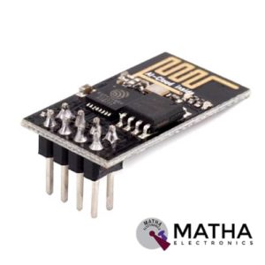
ESP8266 ESP – 01
- 11 b/g/n
- Wi-Fi Direct (P2P), soft-AP
- Integrated TCP/IP protocol stack
- Integrated TR switch, balun, LNA, power amplifier and matching network
- Integrated PLLs, regulators, DCXO and power management units
- +19.5dBm output power in 802.11b mode
- Power down leakage current of <10uA
- 1MB Flash Memory
- Dimensions: 25 x 15 x 11 mm (LxWxH)
- PCB Thickness: 1mm
- Weight: 2 gm
- SDIO 1.1 / 2.0, SPI, UART
- STBC, 1×1 MIMO, 2×1 MIMO
- A-MPDU & A-MSDU aggregation & 0.4ms guard interval
- Wake up and transmit packets in < 2ms
- Standby power consumption of < 1.0mW (DTIM3)
- Integrated low power 32-bit CPU could be used as an application processor
- A-MPDU & A-MSDU aggregation & 0.4ms guard interval
- Wake up and transmit packets in < 2ms
- Standby power consumption of < 1.0mW (DTIM3)

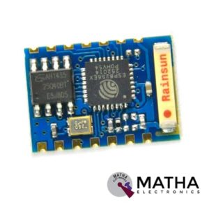
ESP8266 ESP – 03 WIFI Transreceiver Wireless Module
- Communication interface voltage: 3.3V
- Working current: 240mA(MAX)
- 802.11 b/g/n
- Wi-Fi Direct (P2P), soft-AP
- Integrated TCP/IP protocol stack
- Integrated TR switch, balun, LNA, power amplifier and matching network
- Integrated PLLs, regulators, DCXO and power management units
- +19.5dBm output power in 802.11b mode
- Power down leakage current of <10uA
- Integrated low power 32-bit CPU could be used as application processor
- SDIO 1.1/2.0, SPI, UART
- STBC, 1×1 MIMO, 2×1 MIMO
- A-MPDU & A-MSDU aggregation & 0.4ms guard interval
- Wake up and transmit packets in < 2ms
- Standby power consumption of < 1.0mW (DTIM3)
- SDIO 2.0, SPI, UART
- 32-pin QFN package
- Integrated RF switch, balun, 24dBm PA, DCXO, and PMU
- Integrated RISC processor, on-chip memory and external memory interfaces
- Integrated MAC/baseband processors
- Quality of Service management
- I2S interface for high fidelity audio applications
- On-chip low-dropout linear regulators for all internal supplies
- Proprietary spurious-free clock generation architecture
- Integrated WEP, TKIP, AES, and WAPI engines


ESP8266 ESP-12E
- LDR Light Sensor on board.
- WS2812 Led on board.
- Wireless Standard: IEEE 802.11 b/g/n protocol
- Frequency Range: 2.412 - 2.484 GHz
- Serial Transmission: 110 - 921600 bps, TCP Client 5
- SDIO 2.0, SPI and UART Interface available
- PWM available
- One ADC channel is available
- Programmable GPIO available
- Wireless Network Type: STA / AP / STA + AP
- Security Type: WEP / WPA-PSK / WPA2-PSK
- Encryption Type: WEP64 / WEP128 / TKIP / AES
- Network Protocol: IPv4, TCP / UDP / FTP / HTTP
- Operating Voltage: 3.3V
- Maximum current allowed to draw per pin: 15mA
- Power down leakage current of < 10uA
- Integrated low power 32-bit MCU
- Onboard PCB Antenna
- Wake up and transmit packets in < 2ms
- Standby power consumption of < 1.0mW
- Operating Temperature: -40ºC to +125 ºC

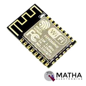
ESP8266 ESP-12F
- Communication interface voltage: 3.3V
- Working current: 240mA(MAX)
- Serial port baud rate: 115200 (default), can be modified to other values by AT command
- Serial communication format: 8N1
- Wireless Network Mode: station / softAP / SoftAP + station
- Wireless criteria: 802.11 b / g / n
- WIFI @ 2.4 GHz, support for WPA / WPA2 security mode
- +19.5dBm output power
- Compatible with ESP-12(ESP-202)
- It is very easy to develop projects with AT commands
- Surface Mount Package with 2mm Pitch Pads
- Mulitple GPIO’s for all your sensor needs
- Integrated TCP/IP protocol stac
- Integrated TR switch, balun, LNA, power amplifier and matching network
- Integrated PLL, regulators, DCXO and power management unit
- Power down leakage current of <10uA
- Integrated low power 32-bit CPU could be used as an application processor
- SDIO 1.1/2.0, SPI, UART
- STBC, 1×1 MIMO, 2×1 MIMO
- A-MPDU & A-MSDU aggregation & 0.4ms guard interval
- Wake up and transmit packets in < 2ms
- Standby power consumption of < 1.0mW (DTIM3)
- Both SMD and Inline package are available, and the pin pitch is 2.0mm.


ESP8266 Serial Wifi module Adapter Plate

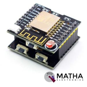
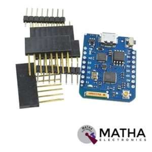
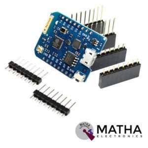
ESP8266 Serial WIFI Witty Cloud Development Board ESP-12F Module MINI Nodemcu
- LDR Light Sensor on board
- WS2812 Led on board
- 3x tactile buttons (1x in the Witty board and 2x in theCH340 board)
- Micro USB connection for power and/or programming
- Uses latest ESP-12F module with 4M flash and integrated antenna
- Includes CH340G USB-to-UART programmer
- Includes LDR (light dependent resistor a.k.a photoresistor) connected to ESP’s ADC pin
- RGB LED connected to GPIO 12,13 and 15
- It supports 3 modes AP, STA, AP+STA

ESP8266 WIFI Industrial stable version A full test board cloud function test Black board T5
- Support 802.11b / n / g wireless standard
- Independent development MCU platform
- High cost performance
- Support UART / GPIO data communication interface
- Support STA / AP / STA + AP coexistence mode of operation
- Support SmartLink intelligent networking (APP)
- Support wireless upgrade firmware
- Support WPS network configuration
- Built-in onboard antenna &Temperature and humidity sensor
- RGB three-color light adjustable
- Provide rich AT command set configuration
- Free AiCloud cloud service for debugging
- 3 AA batteries / 5V adapter power supply
- Size: 61.6mm x 56.2mm;


ESP8266 WIFI Shield
- Operating voltage 5V (supplied from the Arduino Board)
- Connection via: 802.11b/g networks
- Encryption types: WEP and WPA2 Personal
- Connection with Arduino on SPI port
- on-board micro SD slot
- ICSP headers
- FTDI connection for serial debugging of WiFi shield
- Mini-USB for updating WiFi shield firmware
- 32-bit RISC architecture
- The processor can operate at 80MHz / 160MHz
- 32MB flash memory
- 64kB for instructions
- 96kB for data
- Operates in AP, Station or AP + Station mode
- It has 11 digital pins
- It has 1 analogue pin with 10-bit resolution
- Digital pins except the D0 have interrupts, PWM, I2C and one wire
- Programmable through USB or WiFi (OTA)
- Compatible with Arduino IDE
- Compatible with modules and sensors used in Arduino
ESP8266- 01 5V WIFI RELAY MODULE TOI APP CONTROLLED FOR SMART HOME AUTOMATION
- Onboad module: ESP2866 WIFI module
- Onboard relay: 5v.10a/250v ac, 10a/30v dc
- Can connect 5 clients at the same time on AP mode
- The module has two work modes: Cell phone, carry on Wi-Fi module and Cell phone and Wi-Fi module carry on the same router
- Used in mobile phone, Wi-Fi module equipped with one router and control relay by APP
- Maximum transmission distance of 400 m when cell phone carry on wifi module directly, in the open environment
- Transmission distance depends on routers signal intensity when wifi and cell phone is carrying on the same router
- IN+, IN_: 5V power input
- TX, RX, and GND: serial port debug pins
- Baud rate: 115200
- Provide diode effusion protection
- Short response time
- Dimension: 45*28mm
ESP8266-12E 10A 220V NETWORK RELAY WIFI MODULE INPUT DC 7V-30V
- Input voltage: DC 7V-30V
- Relay voltage: 220V
- Relay current: 10A
- ISM: 2.4GHz
- PA: +25dBm
- Input over-voltage protection
- Input overcurrent protection
- ESP8266 WIFI module with 4 layered board design
- LED indicator for input status and output status
- 220V 10A relay, normally opened, and one normally closed
- Optocoupler isolation input, TVS input protection
- Access server control via HTTP protocol by TCP client mode, high current terminals
- Dimension: 65*40*18mm
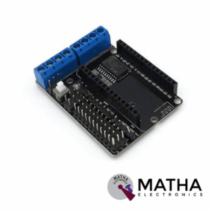

L293D Motor Driver Board for ESP8266 WiFi NodeMcu Lua ESP12E
- Motor power supply Range: 4.5V ~ 36V
- Control power Range: 4.5V ~ 9V (10VMAX)
- Logic Operating current: ≤60mA
- Drive part of the work current Io: ≤1.2A
- Maximum power dissipation: 4W
- Drive Type: Dual high-power H-bridge driver
- Working temperature: -25 ℃ ~ + 125 ℃
- ESP12 DEV KIT development board expansion module
- Lead ESP12 DEV KIT all the features of pins: SPI, UART, GPIO, AI, and 3.3V power connector
- Extend two-way motor-driven, two-way direct-drive motor
- on board power switch
- Motor power, control power separation
- Dimension: 60 x 45 x 13mm


LOLIN32 V1.0.0 ESP32 Rev1 Wifi Bluetooth Board
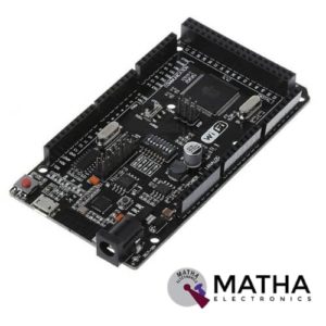
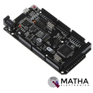
Mega R3 +WiFi ATmega2560+ESP8266 Module CH340G Compatible For Arduino Mega
- Microcontroller:ATmega2560
- IC Wi-Fi : ESP8266
- USB-TTL converter: CH340G
- Power Out: 5V-800mA
- Power Input USB: 5V (500mA max.)
- Power Input VIN/DC Jack: 9-24V
- Power Consumption: 5V 800mA
- Logic Level: 5V
- Wi-Fi 802.11 b/g/n 2.4 GHz
- USB: Micro USB
- Clock Frequency: 16MHz
- Operating Supply Voltage: 5V
- Digital I/O: 54
- Analog I/O: 16
- Memory Size: 256kb
- Data RAM Type/Size: 8Kb
- Data ROM Type/Size: 4Kb
- Interface Type: SerialOTA
- Operating temperature:−40С°/+125С°
- Build in external antenna
- Dimensions:53.361×101.86mm


Mini ESP-M2 ESP8285 Serial Wireless WiFi Transmission Module SerialNET MODE Fully Compatible With ESP8266
ESP8285 M2 WiFi IoT Module :
- SOC characteristics.
- Built-in Tensilica L106 ultra-low power 32-bit CPU, main frequency supports 80MHz and160MHz and RTOS.
- Built-in TCP/IP protocol.
- Built-in one-channel 10-bit high precision ADC.
- Outboard interface: HSPI, UART, I2C, I2S, IR Remote Control, PWM, GPIO.
- The deep sleep current is 10uA, the cut-off current is smaller than 5uA.
- Wake, connect and transmit data package within 2ms.
- The consumer power is smaller 1.0Mw (DTIM3) when at standby status.
- Built-in 1M byte for SPI Flash.
- Ultra-small size.
- Support serial to WiFi.
- Wireless transparent transmission.
- Long-distance transmission with ultra-low power.
- Support outboard antenna.
- Bearing high temperature to 125 °C, compared to the 85°C for ESP8266.
- Support 802.11 b/g/n/e/I.
- Support Station, Soft AP, Soft AP+STA mode.
- Support WiFi Direct (P2P).
- Support CCMP (CBC-MAC, computation mode), TKIP (MIC, RC4), WAPI (SMS4), WEP (RC4), CRC etc., for hardware acceleration.
- P2P finding, P2P GO mode/ GC mode and P2P power management.
- WPA/PA2PSK and WPS.
- 11securitycertification: pre-certification and TSN.
- Support 802.11n (2.4GHz).
- 1h/RFC1042 frame encapsulation.
- Support seamless roaming.
- Support AT remote update and cloud update (OTA).
- Support Smart Config function (including Android and Ios device


MINI NODEMCU ESP8266 WIFI DEVELOPMENT BOARD BASED ON ESP-12F
- Communication interface voltage: 3.3V
- Working current: 240mA(MAX)
- Serial port baud rate: 115200 (default), can be modified to other values by AT command
- Serial communication format: 8N1
- Wireless Network Mode: station / softAP / SoftAP + station
- Wireless criteria: 802.11 b / g / n
- WIFI @ 2.4 GHz, support for WPA / WPA2 security mode
- +19.5dBm output power
- Compatible with ESP-12(ESP-202)
- It is very easy to develop projects with AT commands
- Surface Mount Package with 2mm Pitch Pads
- Multiple GPIO’s for all your sensor needs
- Integrated TCP/IP protocol stack
- Integrated TR switch, balun, LNA, power amplifier and matching network
- Integrated PLL, regulators, DCXO and power management unit
- Power down leakage current of <10uA
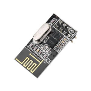
Mini SMD NRF24L01 2.4G Wireless Data Transmission Module
- Maximum operating speeds up to 2Mbps
- GFSK modulation efficiency, Anti-interference ability,
- Built-in hardware CRC error detection, Multipoint communication address control.
- Low-power 1.9 to 3.6V, only 1uA on Power-down mode
- Built-in 2.4Ghz antenna
- Built-in voltage regulator
- 125 Channels, Multi-point communication, and frequency hopping to meet the communication needs
- Wireless transceiver including Frequency generator, enhanced type, SchockBurstTM, mode controller, power amplifier, crystal amplifier, modulator, demodulator
- The output power channel selection and protocol settings can be set extremely low current consumption, through the SPI interface
- In the transmit mode, the transmit power is 6dBm, the current is 9.0mA, the accepted mode current is 12.3mA, the current consumption of the power-down mode and standby mode are lower
- Standard DIP Pitch Interface for embedded applications.NRF24L01 SPI interface: hardware SPI port, MCU I/O ports
- Internal FIFO compatible with a variety of microprocessor interface, micro-controller is convenient


Mini Ultra-small Size ESP-M3 From ESP8285 Serial Wireless WiFi Transmission Module Fully Compatible With ESP8266
- Model: ESP8285 ESP-M3
- 32-bit Tensilica L106 microcontroller
- Ultra-low 16 bit RISC
- Fully Compatible with ESP8266
- Embedded TCP protocol
- channel high-precision 10-bit ADC
- Supporting the most commonly used networks (802.11 b / g / n)
- Support WPA, PA2PSK and WPS
- Working temperature: -40 ℃ - + 125 ℃
- Clock Speed: 80 MHz; (max 160 MHz)
- Flash memory: 1 MB
- Interface: HSPI, UART, I2C, I2S, Remote Control IR Control, PWM, GPIO
- Direct WiFi Support (P2P)
- Support mode: CCMP, TKIP (MIC, RC4), WAPI (SMS4), WEP (RC4), CRC etc
- Low consumption
- Easy access to the pins


NODMCU Esp8266-12 USB CP2102
- 11 b/g/n Wi-Fi Direct (P2P), soft-AP
- Integrated TCP/IP protocol stack
- CP2102 Serial / USB Chip
- +19.5dBm output power in 802.11b mode
- 4MB Flash Memory
- Integrated low power 32-bit CPU
- SDIO 1.1 / 2.0, SPI, UART
- Dimensions – 49 x 24.5 x 13mm
- Integrated TR switch, balun, LNA, power amplifier and matching network
- Integrated PLLs, regulators, DCXO and power management units
- On board USB to serial chip to easily program and upload codes from the Arduino IDE
- Embeds logic level converter circuits
- Has on board 3.3V regulator to ensure enough power to function as your go-to WiFi chip!
- Easy access to the GPIO pins for easy prototyping
- ESP-12E Processor
- Easy to use breadboard friendly form factor
- Voltage Regulator / Converter, excellent DC to DC conversion, super efficientESP-12E Processor
- Easy to use breadboard friendly form factor

NRF24L01 Long Range
- Voltage: 3-3.6V (recommended 3.3V) V.
- Maximum output power: +20dBm.
- Power-down mode current: 4.2uA.
- Operating Range: 1Km.
- Transmission mode current(peak): 115mA
- Receiver Mode Current(peak): 45mA
- Power-down mode current: 4.2uA
- Sensitivity 2Mbps mode in received: -92dBm
- It uses 2.4GHz global open ISM band, with license free.
- SPI interface facilitates the communication with MCU I/O port.
- Support six-channel data reception.
- 2Mbit/s speed makes high-quality VoIP possible
- Multi-frequency points: 125 frequency points meet the needs of multi-point communications and frequency hopping.
- Supports 126 RF channels
- Onboard antenna for optimum performance
- Standard DIP type pinout for easy Interface through jumper wires or breadboard
- Small size: 16.5mm*45.5mm.
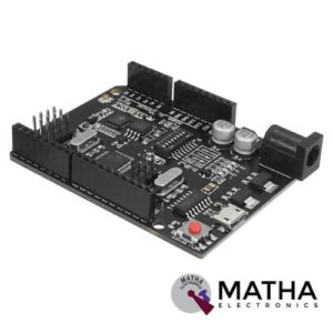

UNO R3 +WiFi ATmega328P+ESP8266 Module CH340G Compatible For Arduino Uno
- Microcontroller: ATmega328IC
- Wi-Fi: ESP8266
- USB-TTL converter: CH340G
- Power Output: 5V-800mA
- Power input USB: 5V (500mA max.)
- Power input VIN/DC Jack: 9-24V
- Power Consumption: 5V 800mA
- Logic Level: 5V
- WiFi: 802.11 b/g/n 2.4 GHz
- USB type: Micro USB
- USB Clock Frequency: 16MHz
- Operating Supply Voltage: 5V
- Digital I/O Pins: 14
- Analog I/O pins: 6
- Memory Size: 32Mb
- Interface Type: serial
- Operating temperature: −40С°/+125С°
- Dimensions (L×W)mm: 53.34×68.58
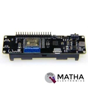
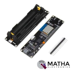
WeMos D1 ESP Wroom 02 Board ESP8266 Mini WiFi Nodemcu Module 18650 Battery
- One AD inputs.
- Micro USB inputs.
- One programmable LED (D0).
- AUTO PROGRAM circuit.
- ESP8266 (ESP-WROOM-02 With TELEC) is equivalent to the NodeMCU.
- Analog Input (AD): Built-in dividing resistor (AD = 220K ADC 100K = GND).
- There is a SOLDER terminal for SLEEP MODE.
- Compatible With Arduino andNodeMCU.
- Operation and charging are possible at the same time.
- 18650 charging circuit including the 5V boosting circuit with TP5410.
- Overcharge protection, over-discharge protection built-in.
- LED: Red = Charging, Green = Full charging.
- 3000 mA 18650 It is possible to operate for more than 17 hours on a battery.
- Integrated 18650 battery charging and discharging system.
- One switch controls whether the 18650 battery is on power or not.
- OLEDs SDA and SCL can connect to the D1 pin and the D2 pin respectively.
- The five buttons can be controlled by FLATH, RSET, D5, D6, and D7 respectively.
- The 5 Digital pins can configure the write/read/interrupt/PWM/I2C/one-wire supported separately.
- Operation and NodeMCU consistent, adding a programmable LED, you can use GPIO16 to control; display 8266 running status and other functions. Integrated OLED and five buttons, more convenient for development.
- The design concept originates from the open-source project NodeMCU; the development board integrates 18650 charging and discharging systems with charging and discharging protection. At the same time, an OLED and five directional buttons are integrated to facilitate the development.