
I am text block. Click edit button to change this text. Lorem ipsum dolor sit amet, consectetur adipiscing elit. Ut elit tellus, luctus nec ullamcorper mattis, pulvinar dapibus leo.
-20%


RFID 13.56MHz Card
Original price was: ₹45.00.₹35.00Current price is: ₹35.00. inc. GST
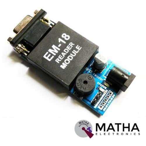
RFID EM18 125KHz RS232 Output
Original price was: ₹600.00.₹500.00Current price is: ₹500.00. inc. GST
SIM800A Quadband GSM / GPRS Module convertible as Shield for Arduino
Original price was: ₹1,500.00.₹1,200.00Current price is: ₹1,200.00. inc. GST
- Quad-Band GSM/GPRS 850/ 900/ 1800/ 1900 MHz.
- GPRS class 2/10.
- Input Voltage: 9V-12V DC.
- Control via AT commands (3GPP TS 27.007, 27.005 and SIMCOM enhanced AT command set).
- Configurable baud rate.
- Built-in SIM Cardholder.
- Built-in Network Status LED.
- 5V interface for direct communication with MCU kit.
- Inbuilt Powerful TCP/IP protocol stack for internet data transfer over GPRS.
- Low power.
- SMA connector with GSM L Type Antenna.
- Headphone jack for audio out.
- Li-Po battery 3.7-volt pins for supply.
- Li-Po battery USB charger (3.7volts).
- CP2102 port for communication with a laptop.
Description
This module designed with SIMCOM Makes the SIM800 Quad-band GSM/GPRS engine, which operates on frequencies 850 MHz, 900 MHz, 1800 MHz, and 1900 MHz. This small size and easy to use as a plug-in GSM Modem. Using the AT command the baud rate is configurable from 9600-115200. And it can transmit Voice, SMS, and data information with low power consumption. Firstly the Modem is in Auto baud mode. Hence the modem needs only two wires (Tx, Rx) except the Power supply to interface with the microcontroller/Host.
The SIM800A Quad-Band GSM/GPRS Module with RS232 Interface is a complete Quad-band GSM/GPRS solution in an LGA(Land grid array) type which can be embedded in the customer applications. It measures 100 x 53 x 15 mm, which can easily fit into the slim and compact demands of custom design.
Moreover, this SIM800A modem built with SIM800A GSM chip and RS232 interface ensures easy connection with the computer or laptop. This was achieved using the USB to the Serial connector or to the microcontroller using the RS232 to TTL converter. Once the SIM800A modem is connected using the USB to RS232 connector, the correct COM port from the Device Manager of the USB to Serial Adapter should be identified.
After that, you can open Putty or any other terminal software. Thereafter, open a connection to that COM port at 9600 baud rate, which is the default baud rate of this modem. Once a serial connection is open through the computer or your microcontroller, start sending the AT commands. When an AT command is sent for example “or” you should receive back a reply from the SIM800A modem saying “OK” or other response depending on the command sent.
Application :
- Remote POS (point of sale) terminals.
- Traffic signals monitor and control.
- Fleet management.
- Power distribution network supervision.
- Central heating system supervision.
- The weather station data transmission.
- Hydro-logic data acquisition.
- Vending machine.
Reviews (0)
Shipping & Delivery

Related products

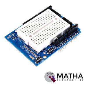
Arduino Compatible Nokia 5110 Prototype Proto Shield Expansion Board
- Supports Nokia5110 display
- Standard 0.1"x0.1" prototyping grid with big pads
- Comes with Stacking headers and plain header, choose whichever you want when soldering together
- IC pattern for adding DIP ICs up to 20 pins
- Power rails down the middle and sides
- Reset button and an extra general use button
- 2 3mm general use LEDs, red and green, as well as 2 matching resistors
- A pass-thru ICSP stacking header so you can stack any kind of shield on top, and/or use an AVR programmer
- Surface-mount chip area for up to 14 SOIC size parts
- Compatible with tiny breadboards
- Every pin is brought out
- Gold plated pads
- 2 x 0.1uF capacitors on either side for extra power stability

DTMF Shield
- MT8870 Decoder IC.
- 4 Output digital pins.
- Operates on 5V
- Includes MT8870 DTMF Receiver IC
- Receives and Converts Standard DTMF Codes
- Remotely Switch Devices from Anywhere Using the Phone
- Easily Connects to Most Microcontrollers or Roboduino Board
- Low Power Consumption
- 5 On-Board LED's For Data Received Indication
- Standard Header Connections for Control System Connection
- Audio socket for application
- Speaker connector for audio sound checking.
- Microphone connector for over the air remote control system( note, due to environmental noise, without any filtering system this method is not recommended)
- Dimension: 37x37x9mm


Dual Monster Moto Shield VNH2SP30 Motor Driver 2x14A (Peak 30A)
- Driver Model: VNH3ASP30
- Current sensing available to Arduino analogue pin
- Operating Voltage: 12 V to 16V DC
- Peak Current: 14A
- Continuous Current: 30A
- of Channels: 2
- Maximum PWM frequency: 20 kHz
- MOSFET on-resistance: 19 m (per leg)
- Thermal Shutdown protection
- Under-voltage and Overvoltage shutdown.
- LED Indicator
- Dimensions: 60 x 54 x 12mm
- Weight: 19gm


ESP8266 WIFI Shield
- Operating voltage 5V (supplied from the Arduino Board)
- Connection via: 802.11b/g networks
- Encryption types: WEP and WPA2 Personal
- Connection with Arduino on SPI port
- on-board micro SD slot
- ICSP headers
- FTDI connection for serial debugging of WiFi shield
- Mini-USB for updating WiFi shield firmware
- 32-bit RISC architecture
- The processor can operate at 80MHz / 160MHz
- 32MB flash memory
- 64kB for instructions
- 96kB for data
- Operates in AP, Station or AP + Station mode
- It has 11 digital pins
- It has 1 analogue pin with 10-bit resolution
- Digital pins except the D0 have interrupts, PWM, I2C and one wire
- Programmable through USB or WiFi (OTA)
- Compatible with Arduino IDE
- Compatible with modules and sensors used in Arduino


MEGA Sensor Shield V2.0
- PIN13 Stat & Power LED indicator
- Digital IO Ports D0-D53
- Analog IO Ports A0-A15
- Reset Button up to the top
- External Power In
- SD Card Interface
- Ultrasonic Interface
- ISP Interface
- Bluetooth Interface
- APC220 Interface
- PCB finest Immersion Gold processing
- Plug it easier to set up a variety of commonly used module interface

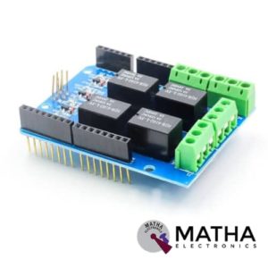
RELAY SHEILD
- Every channel maximum convert voltage: AC 125V / DC 24V
- Every channel maximum converts current: 3A
- Interface via digital I/O pins 4,5,6, and 7
- Relay screw terminals
- Standardized shield shape and design
- LED working status indicators for each relay
- High quality relays
- COM, NO (Normally Open), and NC (Normally Closed) relay pins for each relay
- Update pin SCL, SDA, IOREF, NC.
- Arduino,Crowduino,Seeeduino,Arduino Mega compatible
- Automatic control and manual control
- 4 mechanical relays with photo-coupled circuit
- 3-M3 screw hole easy to install
- Driven by 5V / 3.3V normally open contact close


Sensor Shield V5 Expansion Board For Arduino
- Retain the merits of the V4.0 version
- Laminated design
- PCB immersion gold processing technology
- IIC interface
- Bluetooth module communication interface
- SD card module communication interface
- APC220 Wireless RF modules communication interface
- RB URF v1.1 ultrasonic sensors interface
- 12864 LCD string of line and parallel interface
- 32 servo controller interface
Reviews
There are no reviews yet.