

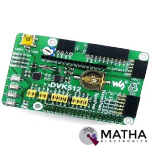
Evaluation Board For Pi
- Designed for Raspberry Pi
- UART interface: easily connects to UART modules such as RS232, RS485, USB TO UART, etc.
- 8 I/Os interface: easily connects to modules controlled by I/Os, such as 8 Push Buttons, Logic Level Converter, Mix Board, etc.
- SPI interface: easily connects to SPI modules such as AT45DBXX Data flash, L3G4200D Board, etc.
- I2C interface: easily connects to I2C modules such as PCF8574 Expansion Board, PCF8563 RTC Board, LSM303DLHC Board, etc.
- Character LCD interface: for connecting character LCDs like LCD1602
- USB connector: USB TO UART, supported by onboard converter CP2102
- Power indicator, User LEDs, User Keys
- Potentiometer: for LCD1602 contrast adjustment
- PCF8563 onboard RTC chip with battery holder and crystal
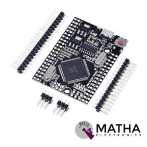

Arduino Mega Pro Mini CH340 Development Board
- Microcontroller ATmega2560
- USB-TTL converter: CH340
- Power Out:5V-800mA
- Power IN.: 5V
- Power IN. VIN/DC Jack:5V
- Power Consumption: 5V 220mA
- Logic Level: 5V
- USB: Micro USB
- Clock Frequency: 16MHz
- Operating Supply Voltage: 5V
- Digital I/O: 54
- Analog I/O: 16
- Memory Size: 256kb
- Data RAM Type/Size: 8Kb
- Data ROM Type/Size: 4Kb
- Interface Type : ISP
- Operating temperature −40С°/+85С°
- Length x Width :38mm×54mm


Arduino Mega 2560 Board
- Microcontroller: ATmega2560
- Operating Voltage: 5V
- Input Voltage (recommended): 7-12V
- Input Voltage (limits): 6-20V
- Digital I/O Pins: 54 (of which 15 provide PWM output)
- Analog Input Pins: 16
- DC Current per I/O Pin: 40 mA
- DC Current for 3.3V Pin: 50 mA
- Flash Memory: 128 KB of which 4 KB used by the boot loader
- SRAM: 8 KB
- EEPROM: 4 KB
- Clock Speed: 16 MHz
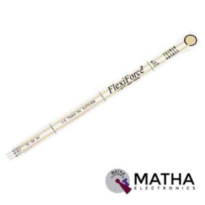
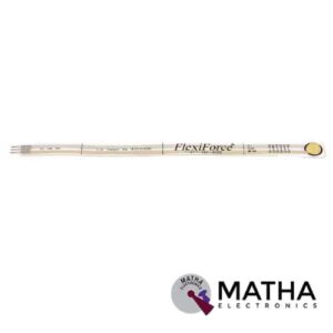
FlexiForce Tekscan A201 Sensor
- Thickness 0.203 mm (0.008 in.)
- Length 191 mm (7.5 in.)** (optional trimmed lengths:
- 152 mm (6 in.), 102 mm (4 in.), 51 mm (2 in.))
- Width 14 mm (0.55 in.)
- Sensing Area 9.53 mm (0.375 in.) diameter
- Connector 3-pin Male Square Pin (centre pin is inactive)
- Substrate Polyester
- Pin Spacing 2.54 mm (0.1 in)
- Small size is ideal for prototyping and integration
- Thin and flexible
- Easy to use

“PWM Generator Module for Stepper Motor Driver with Forward and Reverse Function “
- Board can be used to generate PWM signals for the stepper motor driver
- Operating Voltage: 12VDC
- Three Frequency Range
- Forward and Reverse Function.
- It has three frequency ranges selectable via onboard jumpers.
- Frequency can be measured via PUL and common cathode (GND) ports.
- The board has two sets of power input

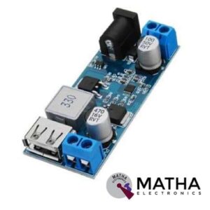

24V/12V to 5V 5A Power Module DC-DC XY-3606 Power Converter
- Working voltage: DC 9V–36V
- Output voltage: 5.2V/5A/25W
- 9~24V input: Output 5.2V/6A/30W
- 24~32V input: output 5.2V/5A/25W
- 32~36V input: output 5.2V/3.5A/18
- The synchronous rectification scheme, wide voltage, high current, high efficiency.
- With DC plug and terminals, easy to use.
- With USB port, fast-charge identification chip compatible with Android and iPhone mobile phones.
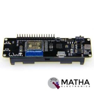
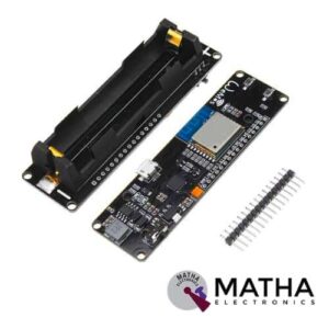
WeMos D1 ESP Wroom 02 Board ESP8266 Mini WiFi Nodemcu Module 18650 Battery
- One AD inputs.
- Micro USB inputs.
- One programmable LED (D0).
- AUTO PROGRAM circuit.
- ESP8266 (ESP-WROOM-02 With TELEC) is equivalent to the NodeMCU.
- Analog Input (AD): Built-in dividing resistor (AD = 220K ADC 100K = GND).
- There is a SOLDER terminal for SLEEP MODE.
- Compatible With Arduino andNodeMCU.
- Operation and charging are possible at the same time.
- 18650 charging circuit including the 5V boosting circuit with TP5410.
- Overcharge protection, over-discharge protection built-in.
- LED: Red = Charging, Green = Full charging.
- 3000 mA 18650 It is possible to operate for more than 17 hours on a battery.
- Integrated 18650 battery charging and discharging system.
- One switch controls whether the 18650 battery is on power or not.
- OLEDs SDA and SCL can connect to the D1 pin and the D2 pin respectively.
- The five buttons can be controlled by FLATH, RSET, D5, D6, and D7 respectively.
- The 5 Digital pins can configure the write/read/interrupt/PWM/I2C/one-wire supported separately.
- Operation and NodeMCU consistent, adding a programmable LED, you can use GPIO16 to control; display 8266 running status and other functions. Integrated OLED and five buttons, more convenient for development.
- The design concept originates from the open-source project NodeMCU; the development board integrates 18650 charging and discharging systems with charging and discharging protection. At the same time, an OLED and five directional buttons are integrated to facilitate the development.


2.8 inch SPI Screen Module TFT Interface 240 x 320 without Touch
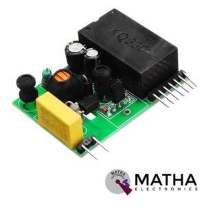
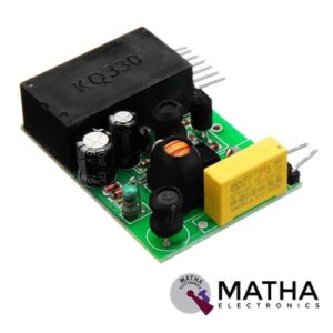
Power Line Carrier Module KQ-430F

Msp-Exp430G2 Msp430 Launchpad
• 14-/20-pin DIP (N) Socket
• 20 pin Launchpad standard leveraging the Booster Pack ecosystem
• On-Board EZ-FET emulator featuring Energy Trace™ technology
• USB debugging and programming interface featuring a driverless installation and application UART
• serial communication with up to 9600 Baud
• Supports MSP430G2xx2, MSP430G2xx3, and MSP430F20xx devices in PDIP14 or PDIP20 packages
• Two general-purpose digital I/O pins connected to green and red LEDs for visual feedback
• Two push button for user feedback and device reset
• Easily accessible device pins for debugging purposes or as socket for adding customized extension boards


CAN Bus Shield
- Implements CAN V2.0B at up to 1 Mb/s
- Industrial standard 9 pin sub-D connector
- OBD-II and CAN standard pinout selectable.
- Changeable chip select pin
- Changeable CS pin for TF card slot
- Changeable INT pin
- Screw terminal that easily to connect CAN_H and CAN_L
- Arduino Uno pin headers
- Grove connectors (I2C and UART)
- SPI Interface up to 10 MHz
- Standard (11 bit) and extended (29 bit) data and remote frames
- Two receive buffers with prioritized message storage